Automatic tin staining device

A tin-dipping, automatic technology, applied in tin feeding devices, auxiliary devices, metal processing equipment, etc., can solve the problems of scalding, low tin dipping efficiency, and difficult to control tin dipping length.

Active Publication Date: 2012-07-25
刘光辉
View PDF7 Cites 59 Cited by
  • Summary
  • Abstract
  • Description
  • Claims
  • Application Information

AI Technical Summary

Problems solved by technology

[0003] At present, when tinning the connection before welding, manual operation is usually used for tinning. On the one hand, the effic

Method used


Image

  • Automatic tin staining device
  • Automatic tin staining device
  • Automatic tin staining device

Examples


Embodiment Construction

[0023] In order to make the purpose, technical solutions and advantages of the invention more clear, the following will clearly and completely describe the technical solutions in the embodiments of the present invention with reference to the accompanying drawings in the embodiments of the present invention. Obviously, the described embodiments are inventions. Some embodiments, not all embodiments. Based on the embodiments of the present invention, all other embodiments obtained by those of ordinary skill in the art without creative work shall fall within the protection scope of the present invention.

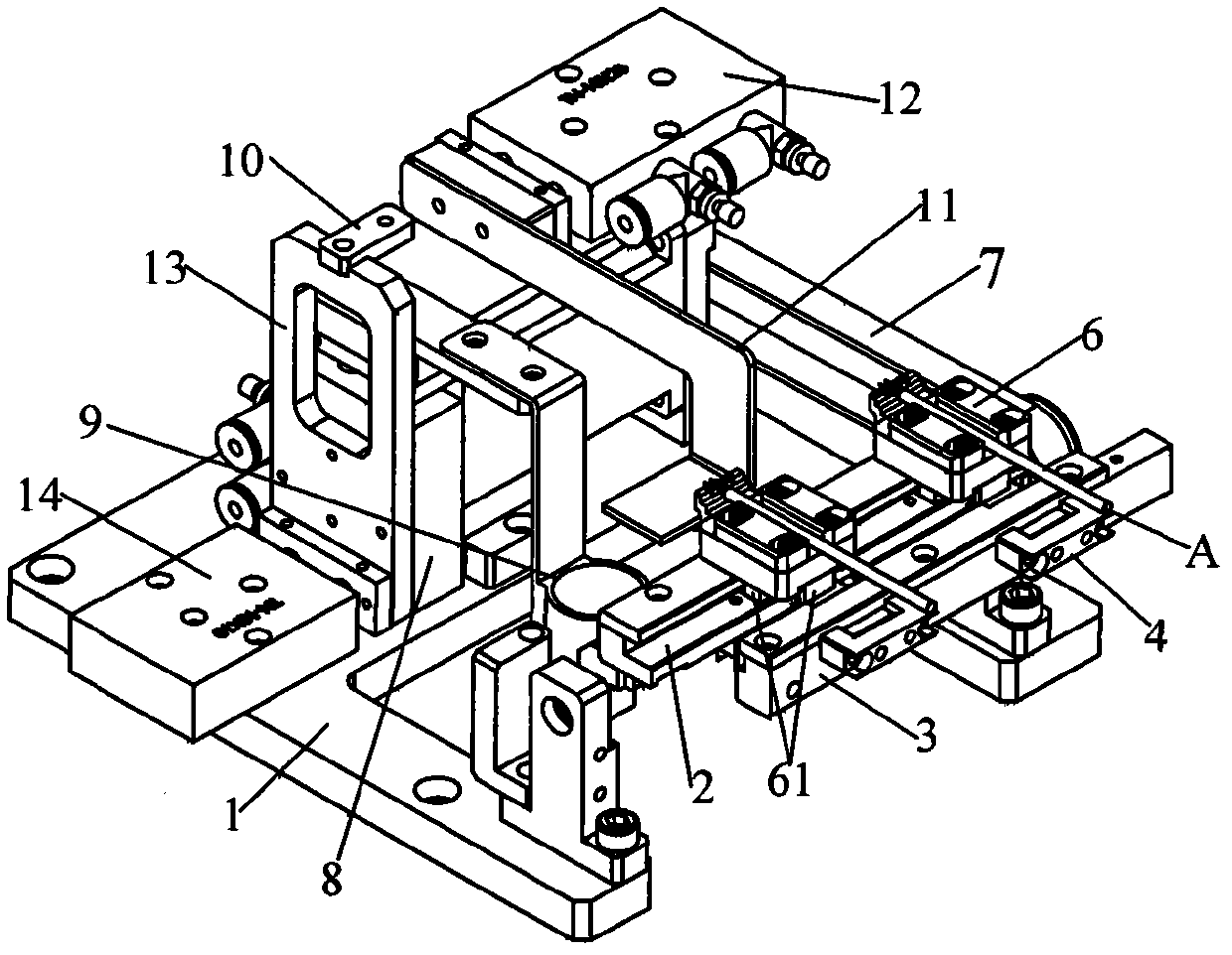
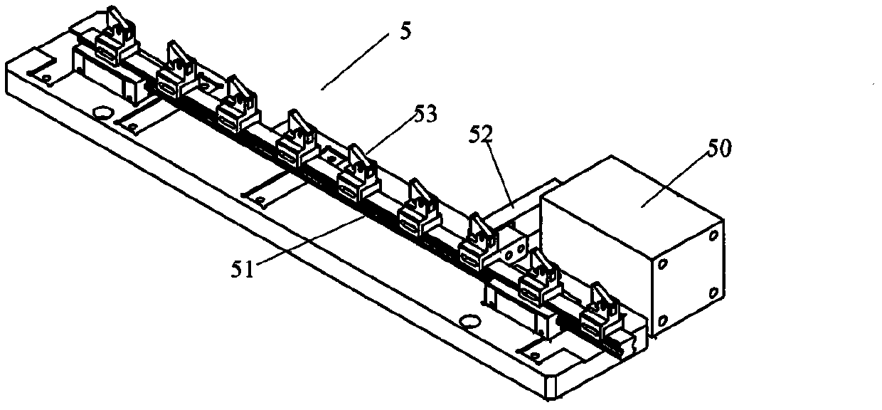
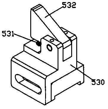
[0024] Such as figure 1 , figure 2 with image 3 As shown, the present invention provides an embodiment of an automatic soldering device.

[0025] The automatic soldering device includes: a conveying mechanism and a tin furnace (not marked in the figure) and a controller that coordinates the operation of pneumatic or / and electric devices (not marked in the figure). The conveying mec...


PUM


Abstract

The invention discloses an automatic tin staining device for a connection line, which comprises a conveying mechanism, a tin furnace and a controller. The controller is used for coordinating the work of a pneumatic or/and electric device; the conveying mechanism is provided with a fixed guide rail mechanism matched with a connection line fixing mechanism, a connection line drive mechanism and a movable guide rail mechanism smoothly connected with the fixed guide rail mechanism; the movable guide rail mechanism is movably connected with a frame and is in transmission connection with a turning mechanism; and the tin furnace is movably arranged on the frame at one side of the movable guide rail mechanism. When the connection line fixed mechanism is moved to a tin staining position during the work, the movable guide rail is turned by the movable guide rail turning mechanism, so that the connection line on the connection line fixed mechanism is reset after being contacted with soldering tin in the tin furnace. The automatic tin staining device is simple in structure, and can accurately control the tin staining length through properly controlling the liquid surface of the soldering tin; simultaneously, the staining of the tin is automatically controlled, so that the efficiency of the staining of the tin can be improved, the low efficiency of the manual staining of the tin is avoided so as not to easily cause scalding phenomenon.

Description

Technical field [0001] The invention relates to the technical field of automatic welding of connecting wires, in particular to an automatic soldering device during the automatic welding of connecting wires. Background technique [0002] The existing connecting wire welding system can automatically connect the connecting wire and the terminal. For example, the automatic welding device for connecting wire and terminal with application number 201010255620.1 and the new automatic welding system for connecting wire of 201120271448.9 can automatically weld the connecting wire. Only one terminal can be welded at a time, and its welding efficiency is low; at the same time, it is necessary to set up automatic soldering and welding torch, its structure is more complicated, there are many control parts, and the debugging is complicated. Therefore, the soldering method can be used to avoid the setting of a soldering device during soldering. [0003] At present, when the connection is dipped b...

Claims


Application Information

Patent Timeline
IPC IPC(8): B23K3/06B23K3/08
Inventor 刘光辉
Owner 刘光辉
Why Eureka
Try Eureka