Chemical mechanical polishing pad and chemical mechanical polishing method

A chemical mechanical and polishing pad technology, applied in the field of polishing, can solve problems such as uneven distribution of polishing pressure, local high-stress scratch damage, local stress peeling, etc., to reduce scratch damage and stress peeling, and reduce scratch damage defects , The effect of reducing the possibility of falling off

Active Publication Date: 2015-02-18
TSINGHUA UNIV
View PDF8 Cites 0 Cited by
  • Summary
  • Abstract
  • Description
  • Claims
  • Application Information

AI Technical Summary

Problems solved by technology

For example, the use of Cu / Low-k materials has become an inevitable trend. If the conventional CMP technology is still used for planarization, due to the difference in strength between the copper wire and the Low-k dielectric material, it will inevitably cause peeling between the copper and Low-k material interface. , the current industry method is to use low pressure (≤2psi) or even ultra-low pressure (≤0.5psi) for polishing. The problem of low output efficiency
In addition, due to the uneven contact between the high-hardness polishing pad and the surface of the polished material during use, it is easy to cause local "hot spots" under the same pressure, causing defects such as local stress peeling and / or scratch damage.
[0005] Chinese patent 200680003086.7 discloses a polishing pad (i.e. polishing pad) for low-pressure grinding, by adjusting the thickness and hardness of the polishing pad grinding layer and the backing layer, to obtain a higher quality surface, but this grinding pad is different from the traditional The polishing pad has no essential difference, and the hardness is still high, so it cannot fundamentally solve the problems of low material removal rate, local stress concentration and scratch damage under low pressure and ultra-low pressure
These thick fibers will still cause uneven polishing pressure distribution under low pressure and ultra-low pressure, which will cause problems such as uneven material removal, local high stress and scratch damage; at the same time, these messy short fibers, in the polishing process In the middle, it is more likely to fall off the surface of the polishing pad, which will further scratch the surface
Therefore, this polishing pad can only meet the CMP requirements of relatively hard materials under conventional pressure (2psi~6psi), and cannot meet the CMP requirements of easily damaged materials such as Cu / Low-k under low pressure and ultra-low pressure.

Method used


Image

  • Chemical mechanical polishing pad and chemical mechanical polishing method
  • Chemical mechanical polishing pad and chemical mechanical polishing method
  • Chemical mechanical polishing pad and chemical mechanical polishing method

Examples


Embodiment 1

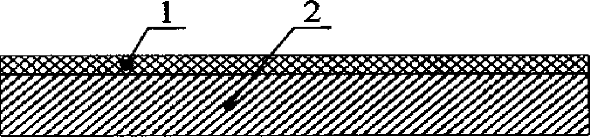
[0031] figure 1 For a specific embodiment of the chemical mechanical polishing pad of the present invention, select commonly used filter paper as the substrate layer 2, adopt the electrospinning method in the prior art to make a layer of nanofiber layer 1 on the surface of the substrate layer 2, the present embodiment The material of the nanofiber layer is polyvinylidene fluoride (PVDF), the thickness of the nanofiber layer is 4 μm, the average fiber diameter is 100 nm, and the fiber length is 20 cm. The polishing pad in Example 1 of the present invention is constituted by the nanofiber layer 1 and the substrate layer 2 .

Embodiment 2

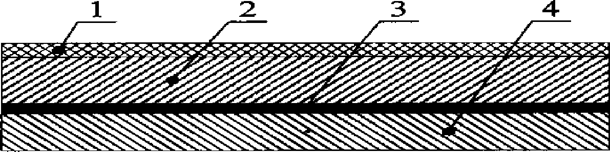
[0033] figure 2 For another specific embodiment of the chemical mechanical polishing pad of the present invention, select the IC1000 polishing pad of Rohm & Haas (Rohm & Haas, the U.S.) as the subpad 4, use the double-sided pressure-sensitive adhesive tape 3 of 3M (3M, the U.S.) The polishing pad in Example 1 of the present invention (consisting of nanofiber layer 1 and substrate layer 2 ) and the sub-pad 4 are connected together to form the polishing pad in Example 2 of the present invention.

Embodiment 3

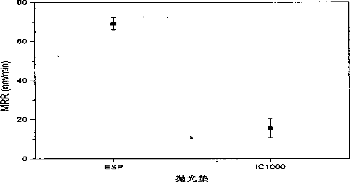
[0035]A kind of specific embodiment of the polishing pad using method of the present invention, use the polishing pad (ESP polishing pad) prepared in the embodiment of the present invention 2, utilize the chemical mechanical polishing equipment that Tsinghua University State Key Laboratory of Tribology makes, cooperate Fujimi 7105 ( Fujimi 7105, Japan) polishing liquid for copper, the pure copper sheet of diameter 12.5mm is polished, and process parameter is as follows:

[0036] Speed ​​(head / plate): 300 / 50RPM

[0037] Eccentric distance: 9mm

[0038] Pressure: 0.5psi

[0039] Polishing fluid dilution ratio: 1:9

[0040] Polishing liquid flow rate: 60mL / min

[0041] Polishing time: 5min

[0042] The performance of the polishing pad prepared in Example 2 of the present invention was evaluated by the material removal rate MRR of the copper sheet being polished and the change in roughness value Ra before and after polishing. Use a Sartorius (Germany) ME235S electronic balanc...


PUM

PropertyMeasurementUnit
thicknessaaaaaaaaaa
lengthaaaaaaaaaa
lengthaaaaaaaaaa

Abstract

The invention discloses a chemical mechanical polishing pad and a chemical mechanical polishing method, belonging to the field of chemical mechanical polishing. The polishing pad at least comprises a nano-fiber layer which is in a non-woven fabric structure, the thickness of the fiber layer is 0.1mum-3cm, the average diameter of a nano-fiber is 1nm-1mum, the length of the nano-fiber is more than 1cm, and the axial direction of the nano-fiber is in parallel to a working surface of the polishing pad. The chemical mechanical polishing method comprises the following steps: a polishing solution is applied on the working surface of the polishing pad or on the surface of a polished material; and the working surface of the polishing pad is in contact with the surface of the polished material, and the polishing pad can move relative to the polished material, so that the chemical mechanical polishing is carried out on the polished material under lower pressure or super-low pressure. With the adoption of the polishing pad, the defects such as scratch damage and stress peeling can be reduced so as to obtain the surface with higher quality; meanwhile, higher material removal speed can be obtained under lower pressure.

Description

technical field [0001] The invention belongs to the technical field of polishing, in particular to a chemical mechanical polishing pad and a chemical mechanical polishing method. Background technique [0002] Chemical Mechanical Planarization / Polishing (CMP for short) is currently considered to be the most effective method for achieving global planarization. The application of CMP has been extended to metal materials (such as Al, Cu, Ti, Ta, W, etc.), dielectric materials (such as SiO 2 、Si 3 N 4 , various Low-k materials, etc.), polysilicon, ceramics, magnetic disks, magnetic heads, and MEMS and other materials or devices. [0003] In the traditional chemical mechanical polishing process, the polishing head carries the wafer under a certain pressure to contact the surface of the polishing pad containing abrasives and chemicals, and the relative movement between the wafer and the polishing pad utilizes the surface of the wafer and the polishing pad and the polishing liqui...

Claims


Application Information

Patent Timeline
Patent Type & Authority Patents(China)
IPC IPC(8): B24B37/24
Inventor 刘宇宏韩桂全雒建斌郭丹路新春
Owner TSINGHUA UNIV
Why Eureka
Try Eureka