
Assembly and disassembly tool for locomotive brake shoe

A brake shoe and locomotive technology, which is applied in the field of locomotive brake shoe disassembly and assembly tools, can solve the problems of inconvenient operation, brake shoe breakage, narrow space, etc., and achieve the effects of avoiding industrial accidents, fixed force arm length, and wide application range

Inactive Publication Date: 2012-07-25
GUANGZHOU INST OF RAILWAY TECH
View PDF9 Cites 1 Cited by
  • Summary
  • Abstract
  • Description
  • Claims
  • Application Information

AI Technical Summary

Problems solved by technology

[0004] Replacing locomotive brake shoes is laborious during locomotive maintenance, so it often happens that the brake shoes are not replaced after they are used to the limit
After the brake shoe is used to the limit, if it is not replaced, the brake shoe is easy to break when the locomotive implements emergency braking. Once the brake shoe breaks during operation, it is very easy to cause the brake shoe to fall off, damage the railway equipment or injure pedestrians, and may even be injured. cause train derailment
[0005] In the prior art, it takes 10 minutes to replace a brake shoe. If it is to replace the brake shoe of the second and fifth moving wheels of the locomotive, because the space there is narrow, the operation is inconvenient, and the force cannot be used, the time required will be longer, and it is easy to replace the brake shoe. dirty hands and body
When workers replace the brake shoes, their hands are covered with sludge and are relatively greasy, which is prone to work-related accidents
Due to the replacement of brake shoes, accidents of fingers being crushed or smashed frequently occur, which poses a major safety hazard

Method used


Image

  • Assembly and disassembly tool for locomotive brake shoe
  • Assembly and disassembly tool for locomotive brake shoe
  • Assembly and disassembly tool for locomotive brake shoe

Examples


Embodiment 1

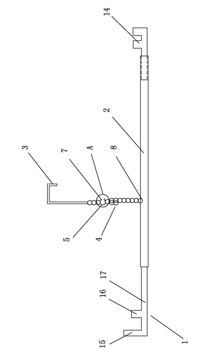
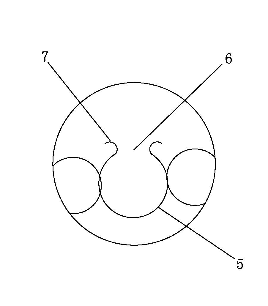
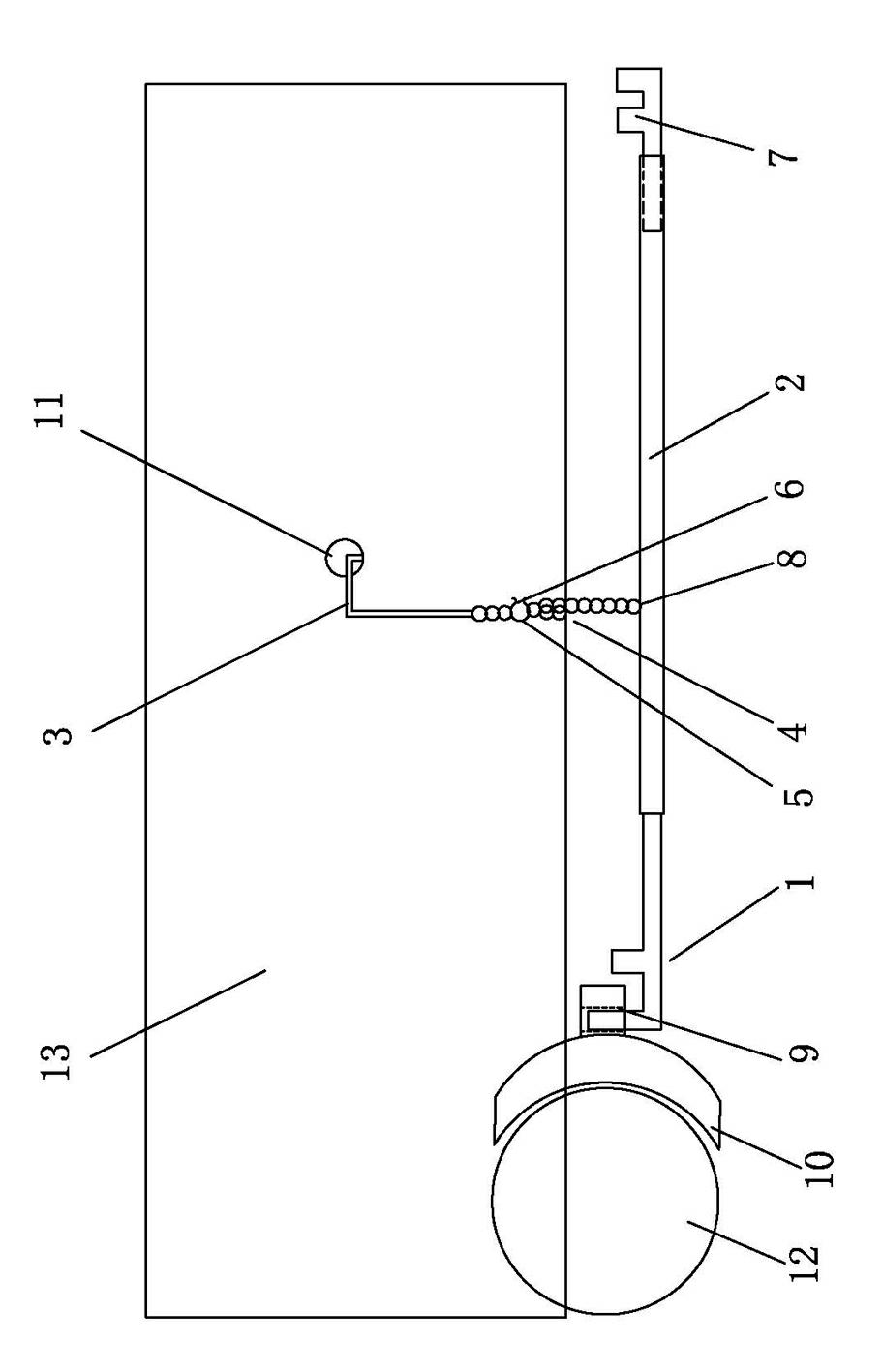
[0046] The described dismounting tool for locomotive brake shoe of the present invention, as figure 1 and figure 2 As shown, it includes a main body and a supporting part, the main body includes a hollow lever 2 and a brake shoe hook 1 with an "F" shape structure, and the brake shoe hook 1 with an "F" shape structure is fixedly connected to one end of the hollow lever 2;

[0047] The support part includes a chain ring group 4 and a hook body 3 , one end of the chain ring group 4 is welded to the hook body 3 , and the other end of the chain ring group 4 is welded to the hollow lever 2 . One end of the chain ring group 4 is directly welded to the hollow lever 2, so that the support part and the main body are connected firmly, and the length of the force arm of the hollow lever 2 is fixed, which is not easy to swing during use, and is convenient to use.

[0048] An adjustment chain ring 5 is arranged on the upper part of the chain ring group 4, and a gap 6 is provided in the mi...

Embodiment 2

[0073] The main technical solutions of the assembly and disassembly tool for locomotive brake shoes in this embodiment are the same as those in Embodiment 1. The features not explained in this embodiment are explained in Embodiment 1, and will not be repeated here. The difference between this embodiment and embodiment 1 is:

[0074] Such as figure 1 As shown, the distance between the welding point 8 where the other end of the chain ring group 4 is welded to the hollow lever 2 is 450 mm from the outermost end of the brake shoe hook 1 of the "F" shape structure, and the other end of the chain ring group 4 is welded to the hollow lever 2. The distance of the welding point 8 from the other end of the lever is 750mm. This distance is based on the best data obtained through trial and error in the weight of the brake shoe 10 and the operator's actual operation, which can save the operator the most effort.

Embodiment 3

[0076] The main technical solutions of the assembly and disassembly tool for locomotive brake shoes in this embodiment are the same as those in Embodiment 1. The features not explained in this embodiment are explained in Embodiment 1, and will not be repeated here. The difference between this embodiment and embodiment 1 is:

[0077] The hollow lever, adjustable wrench, hook body and brake shoe hook are made of stainless steel, such as aerospace square stainless steel welded pipe, the specification is 20mm×20mm×0.8mm, and the material is 304 stainless steel.


PUM


Abstract

The invention relates to the technical field of replacement of locomotive brake shoes, in particular to an assembly and disassembly tool for a locomotive brake shoe, which comprises a body and a support. The body comprises a hollow lever and a brake shoe hook which is of an 'F'-shaped structure, wherein the brake shoe hook which is of the 'F'-shaped structure is fixedly connected with the hollow lever. The support comprises a chain ring group and a hook body, one end of the chain ring group is welded with the hook body, the other end of the chain ring group is welded with the hollow lever, an adjusting chain ring is arranged on the upper portion of the chain ring group, a notch is arranged in the middle of the adjusting chain ring, antislip stop ends are arranged at two ends of the notch respectively, chain rings are mutually in series connection through the adjusting chain ring, the distance from a welding spot of the other end of the chain ring group with the hollow lever to the outermost end of the brake shoe hook which is of the 'F'-shaped structure ranges from 445mm to 455mm, and the distance from the welding spot of the other end of the chain ring group with the hollow lever to the other end of the hollow lever ranges from 740mm to 760mm.

Description

technical field [0001] The invention relates to the technical field of locomotive brake shoe replacement, in particular to a disassembly tool for the locomotive brake shoe. Background technique [0002] The brake shoe is a shoe-shaped brake block made of cast iron or other materials used for locomotives. When braking, it hugs the wheel tread and stops the wheel through friction. In this process, the braking device converts huge kinetic energy into heat energy and dissipates it in the atmosphere. The higher the train speed, the greater the thermal load on the wheels during braking. If cast iron brake shoes are used, the temperature can melt the brake shoes; even if more advanced synthetic brake shoes are used, the temperature will be as high as 400°C to 450°C. When the temperature of the wheel tread increases to a certain level, the tread will be worn, cracked or peeled off, which affects both the service life and driving safety. [0003] During locomotive maintenance, the...

Claims


Application Information

Patent Timeline
IPC IPC(8): B25B27/14
Inventor 曾青中
Owner GUANGZHOU INST OF RAILWAY TECH
Learn More