
Production equipment and method for long fiber reinforced thermoplastic

A technology to strengthen thermoplastic and long fibers, applied in the direction of coating, can solve the problems of not maximizing the infiltration effect, limited work efficiency, limited monofilament spreading, etc., to achieve good impregnation effect, not easy to break, continuous production capacity strong effect

Active Publication Date: 2012-07-25
JURONG BASTEP COMPOSITE MATERIALS
View PDF7 Cites 12 Cited by
  • Summary
  • Abstract
  • Description
  • Claims
  • Application Information

AI Technical Summary

Problems solved by technology

[0006] Both of the above two technical solutions adopt a single-strand raw yarn to enter the impregnation chamber, and use a tension roller to disperse the long-fiber raw yarn. The number is the tex value,) the original yarn, the general number range is between 1200-2400tex, a raw yarn contains about 4000 to 5000 monofilaments, if you need to achieve a good dispersion effect, often need a long dipping There are multiple sets of tension rollers in the cavity for multi-level dispersion, so the work efficiency is greatly limited
In addition, since the tension roller can only disperse the raw yarn in the axial direction of the tension roller, that is to say, the raw yarn passing through the tension roller is only scattered in one dimension, and the monofilament spread is limited, and the soaking effect is not maximized. It is difficult for them to be evenly distributed in the cross-sectional space of the strip during extrusion molding

Method used


Image

  • Production equipment and method for long fiber reinforced thermoplastic
  • Production equipment and method for long fiber reinforced thermoplastic
  • Production equipment and method for long fiber reinforced thermoplastic

Examples


Embodiment Construction

[0038] Below in conjunction with accompanying drawing, the technical scheme of this method is described in detail.

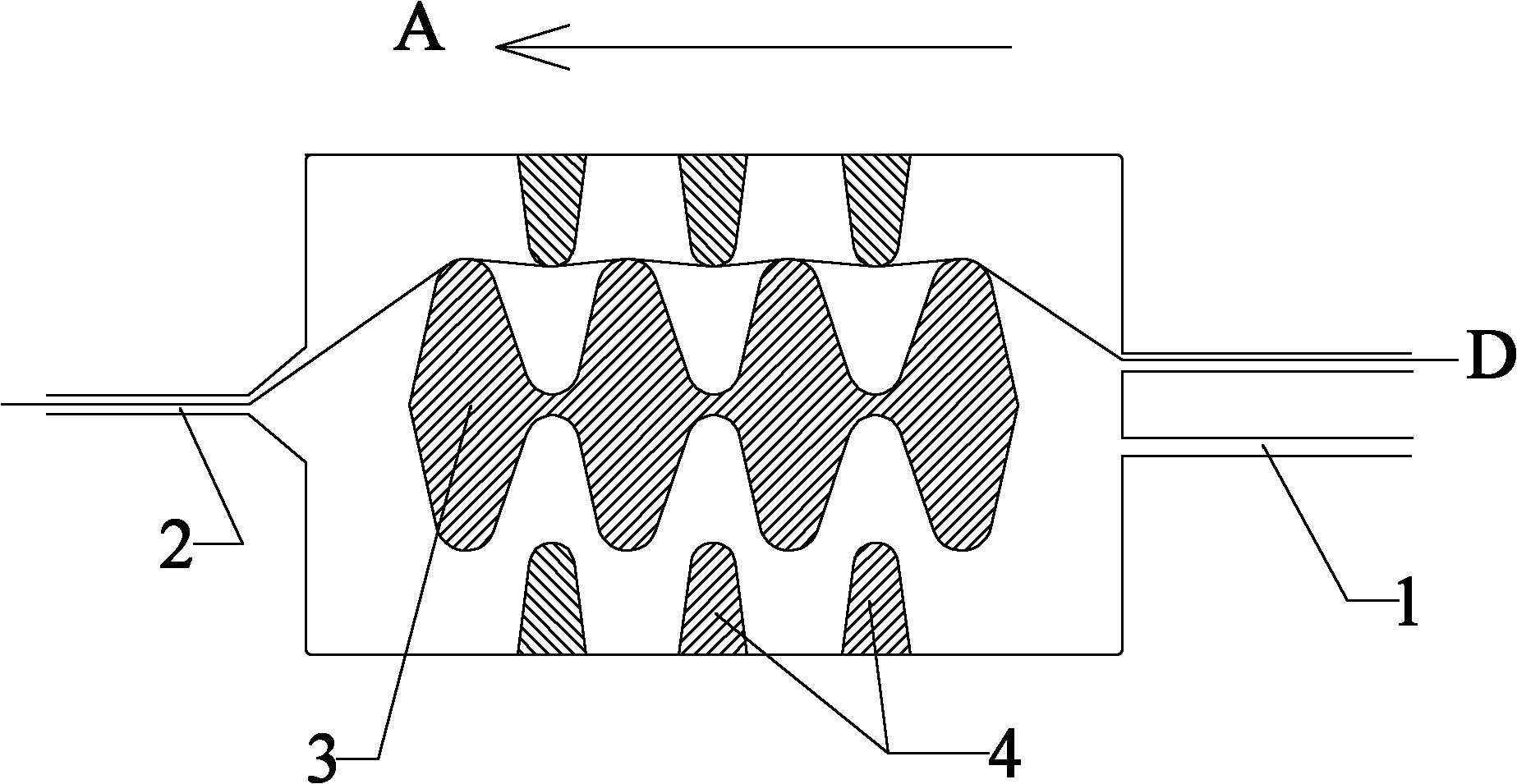
[0039] figure 1 It is a structural schematic diagram of a preferred solution of the raw yarn dispersion structure of the present invention; figure 2 It is a schematic diagram of the three-dimensional structure of another preferred solution of the raw yarn dispersion structure of the present invention; image 3 It is a schematic diagram of the positional relationship between the curve and the straight line forming the core of the loose yarn of the present invention.

[0040] refer to figure 1 and figure 2 , the raw yarn dispersion structure in the present invention comprises more than two yarn feeding through holes 1 whose axes are parallel to each other, and the yarn feeding through holes 1 are distributed centrally symmetrically on a cross section perpendicular to the axial direction, including the axes and the yarn feeding through holes. The axis of the ...


PUM

PropertyMeasurementUnit
Monofilament diameteraaaaaaaaaa

Abstract

The invention discloses a dispersed structure during production of long fiber reinforced thermoplastic when grey yarns are impregnated, an impregnating mould head that uses the dispersed structure and a production method that uses the impregnating mould head. The dispersed structure provided by the invention is provided with a rotary dispersing core that is capable of dispersing the grey yarns effectively, has small abrasion and is not easy to break the mould head. The impregnating mould head that comprises a plurality of impregnating units and uses the structure is convenient to disassemble and has good universality and high efficiency. Compared with prior production method, the production method for long fiber reinforced thermoplastic that uses the impregnating mould head uses multiple strands and units to impregnate so that reinforced fiber is distributed uniformly in the bar (cross section) and ensures that fiber is not exposed so as to improve the production efficiency and quality. Meanwhile, as monofilament is not easy to break the mould head, the continuous production capacity of the production equipment is high.

Description

technical field [0001] The present invention relates to the production equipment and production method of long-fiber reinforced plastics, in particular to an impregnated structure capable of fully dispersing long-fiber raw yarns, and also relates to an impregnated die using the structure, and using the impregnated die to produce long-fiber-reinforced plastics Methods of fiber reinforced plastics. Background technique [0002] Long-Fiber Reinforced Thermoplastic (LFT for short) is a kind of designability, low density, high specific strength, high specific modulus and strong impact resistance. , Fiber-reinforced thermosetting composites pose a huge challenge, and LFT thermoplastics have gradually become mainstream materials for making automotive parts. [0003] In the process of producing LFT, it is necessary to disperse the raw yarn of long fiber materials (such as glass fiber and carbon fiber) into monofilaments in the extruder head so that the molten plastic can be fully i...

Claims


Application Information

Patent Timeline
IPC IPC(8): B29B15/14B29B9/06B29B9/14B29C70/16B29C70/52
Inventor 陆志宏曾天卷
Owner JURONG BASTEP COMPOSITE MATERIALS
Learn More