Multi-row mini-pile enclosing structure for blocking soil and construction process

A technology of enclosure structure and construction technology, which is applied in the direction of foundation structure engineering, excavation, construction, etc., can solve the problems that the enclosure pile construction cannot be unfolded, and the bending stiffness is small, so as to achieve small construction machinery, high bending stiffness, and construction The effect of simple process

Active Publication Date: 2012-07-25
ZHEJIANG SCI-TECH UNIV
View PDF5 Cites 20 Cited by
  • Summary
  • Abstract
  • Description
  • Claims
  • Application Information

AI Technical Summary

Problems solved by technology

[0003] The present invention aims at the disadvantages of the existing foundation pit protection technology that the construction site around the foundation pit is limited, the construction of traditional protection piles cannot be carried out, and the bending stiffness of ordinary mini piles is small. Placed in the direction of the foundation pit wall, the flexural performance of the steel bar

Method used


Image

  • Multi-row mini-pile enclosing structure for blocking soil and construction process
  • Multi-row mini-pile enclosing structure for blocking soil and construction process
  • Multi-row mini-pile enclosing structure for blocking soil and construction process

Examples


Embodiment 1

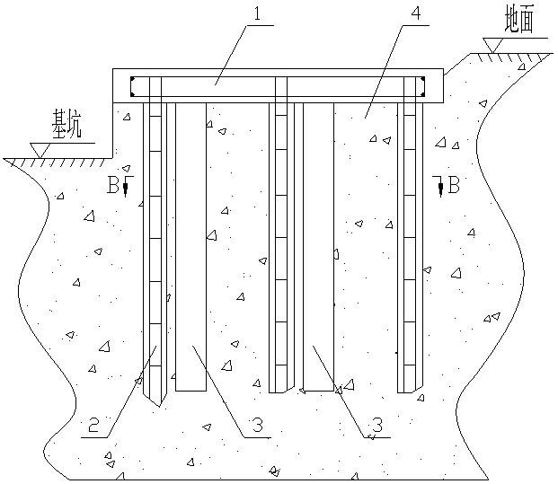
[0031] Multiple rows of mini-pile retaining enclosures, such as Figure 1 to Figure 2 As shown, it includes a crown beam 1 and more than two rows of mini piles 2. The mini piles 2 include a front row of piles 21 and a rear row of piles 22, and a cement-soil mixing pile is arranged between the front row of piles 21 and the rear row of piles 22. 3. The top ends of the mini piles 2 are connected together through the crown beam 1 . Multiple rows of piles are connected with the crown beam 3 to form a unified whole, and the rear row of piles 22 transmits part of the lateral earth pressure to the front row of piles 21 through the crown beam 3 and the soil between the piles, and the passive area provides lateral pressure; at the same time, the front row of piles 21 bears pressure, and the rear row of piles 22 bears tensile force, which generates a certain bending moment, and finally makes the enclosure structure have a higher anti-overturning capability.

[0032] The crown beam 1 is ...

Embodiment 2

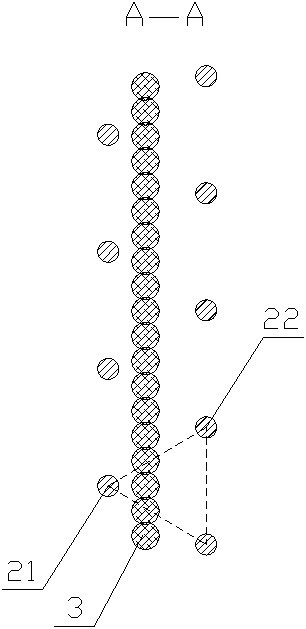
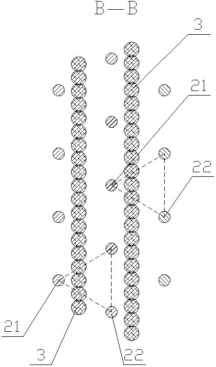
[0049] See image 3 , 4 , the difference between this embodiment and Embodiment 1 is that there are three rows of mini piles 2, and two rows of cement-soil mixing piles 3; Rear row pile 22; When the soil quality is poor or water-stopping requirements are high, multiple rows of mini piles 2 and multiple rows of cement-soil mixing piles 3 can be used to achieve a better anti-seepage effect.

[0050] The construction technology of multi-row mini-pile retaining enclosure includes the following steps:

[0051] a. Excavate a trench around the foundation pit, and the excavation depth is greater than or equal to the design height of the crown beam 1;

[0052] b. Select the position of the pile, locate the pile head, select a geological exploration drilling rig or a bolter drilling rig, and drill through a small-diameter hollow drill bit. While drilling, use a mud wall to protect the pile hole. Different rows of mini piles 2 The pile positions are arranged in a staggered manner, an...


PUM

PropertyMeasurementUnit
Diameteraaaaaaaaaa
Diameteraaaaaaaaaa
Diameteraaaaaaaaaa

Abstract

The invention relates to the field of foundation bases and discloses a multi-row mini-pile enclosing structure for blocking soil and a construction process. The multi-row mini-pile enclosing structure for blocking soil comprises a top beam (2) and more than two rows of mini piles (2), the mini piles (2) comprise front-row piles (21) and rear-row piles (22), cement stirring piles (3) are arranged between the front-row piles and the rear-row piles (22), and the top ends of the mini piles (2) are connected together by the top beam (1). The construction process comprises the steps of digging grooves, positioning pile heads, drilling, grouting, casting and the like. The multi-row piles have the advantages that the whole performance is good, the anti-bending rigidity is high, the lateral deformation of a foundation pit and the surface subsidence of the periphery of the foundation pit can be effectively controlled by an inner support or an anti-pulling anchor rod, the construction time can be saved well and the construction cost is reduced.

Description

technical field [0001] The invention relates to the field of ground foundations, in particular to a multi-row miniature pile retaining enclosure structure and construction technology. Background technique [0002] In order to reduce the impact of foundation pit excavation on the surrounding environment, enclosure piles are widely used in foundation pit enclosure at present. For single-row piles, due to their poor bending resistance, it is difficult to control the displacement of pile tops. Effective control, in order to minimize the impact of foundation pit excavation on the surrounding environment, double-row piles with higher bending resistance are widely used. The traditional double-row piles mainly adopt bored piles and prefabricated piles. However, in view of the current situation of tight land use, the construction site conditions have also become an important condition affecting the type of surrounding piles. Therefore, the bored piles and prefabricated piles Constru...

Claims


Application Information

Patent Timeline
IPC IPC(8): E02D17/04E02D19/08E02D15/04
Inventor 俞峰刘念武李哲辉孔祥冰
Owner ZHEJIANG SCI-TECH UNIV
Why Eureka
Try Eureka