
Supercharged engine and intercooling inlet pipe thereof

A technology for supercharged engines and intake pipes, which is applied to combustion engines, machines/engines, internal combustion piston engines, etc. It can solve the problems of flameout, more condensed water accumulation, and entering the cylinder, so as to increase the gas flow rate and solve the problem of condensed water accumulation Effect

Active Publication Date: 2012-07-25
WEICHAI POWER CO LTD
View PDF5 Cites 3 Cited by
  • Summary
  • Abstract
  • Description
  • Claims
  • Application Information

AI Technical Summary

Problems solved by technology

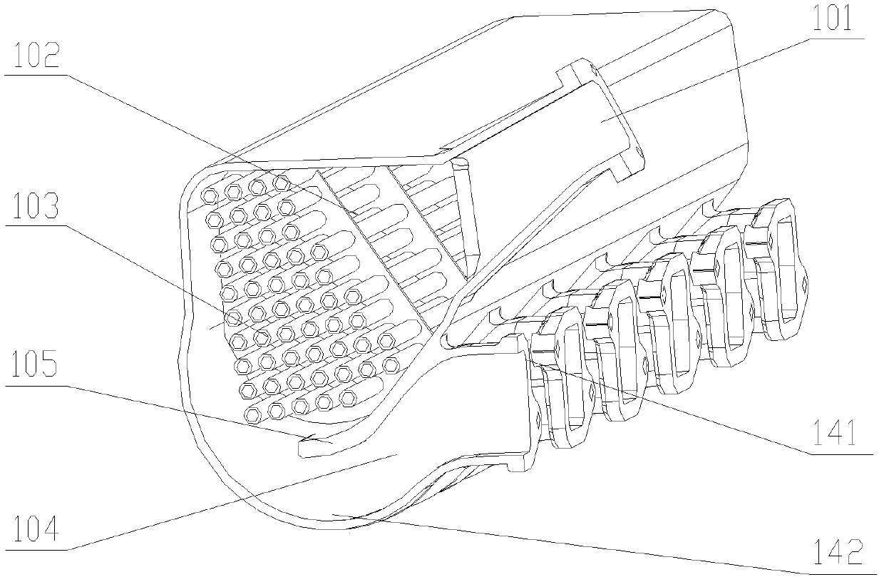
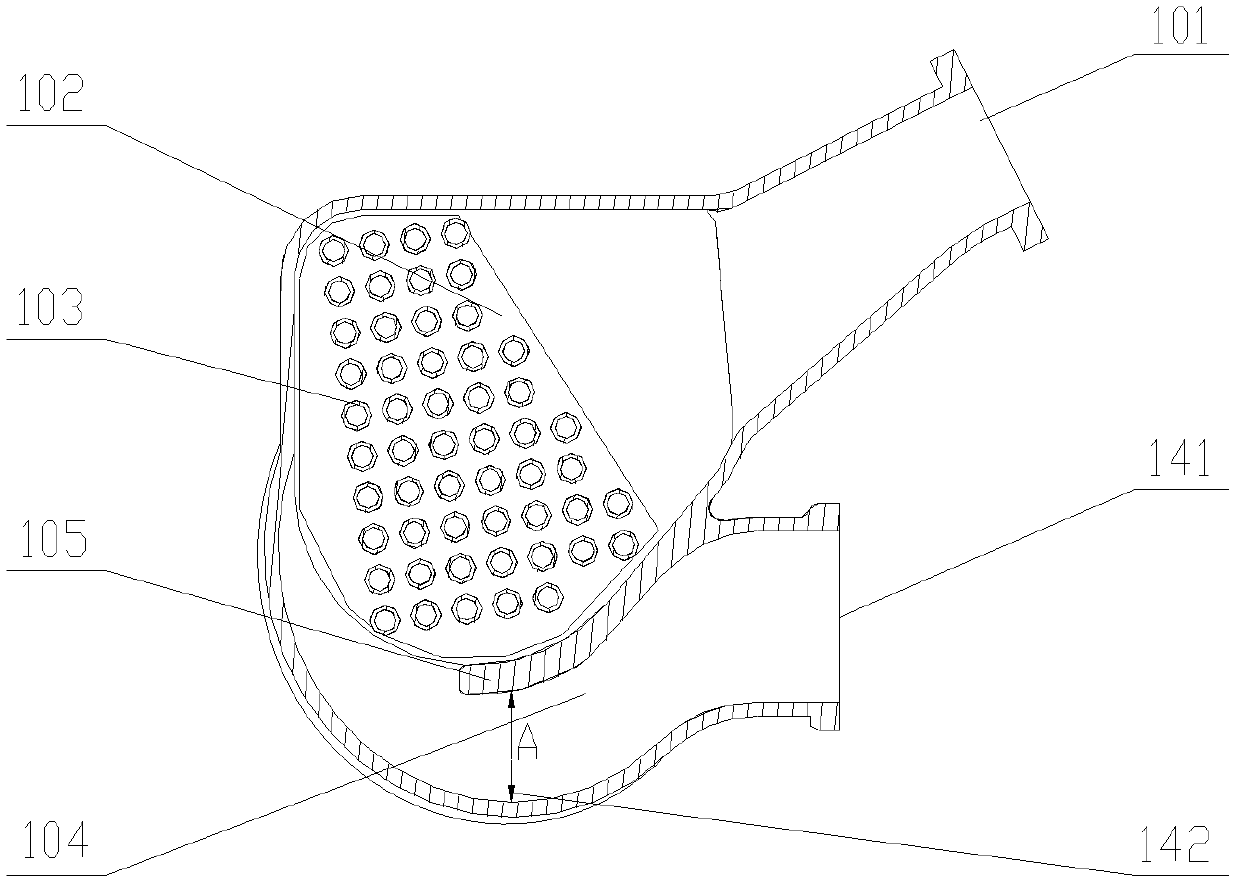
Due to the setting of the partition plate 105 between the intake manifold and the intake manifold 104, the cross-sectional area A of the bottommost end 142 of the intake manifold 104 is smaller than the cross-sectional area of ​​the joint 141 between the intake manifold 104 and the cylinder, so the gas In the process of entering the cylinder through the intake manifold 104, the gas flow rate at the bottommost end 142 of the intake manifold 104 increases, and according to Panoulli's theorem, the pressure at the bottommost end 142 of the intake manifold 104 is less than that of the intake manifold The pressure at the joint 141 between the pipe 104 and the cylinder cannot take away the condensed water accumulated at the bottom end 142 of the intake manifold 104. With the increase of the engine working time, the condensed water will accumulate more and more. After a long time, it will be very May rust the bottommost end 142 of the intake manifold 104
In addition, the accumulation of condensed water is too large, and it is likely to enter the cylinder after parking, which will cause white smoke from the engine, difficulty in starting, and even flameout.

Method used


Image

  • Supercharged engine and intercooling inlet pipe thereof
  • Supercharged engine and intercooling inlet pipe thereof
  • Supercharged engine and intercooling inlet pipe thereof

Examples


Embodiment Construction

[0024] The core of the present invention is to provide an intercooled intake pipe for a supercharged engine. The structural design of the intercooled intake pipe can effectively solve the problem of condensed water accumulation at the bottom of the intake pipe, and dispose of the condensed water before it accumulates. Another core of the present invention is to provide a supercharged engine comprising the above-mentioned intercooled intake pipe.

[0025] In order to enable those skilled in the art to better understand the solution of the present invention, the present invention will be further described in detail below in conjunction with the accompanying drawings and specific embodiments.

[0026] It should be noted that the orientation words such as up, down, left, and right involved in this article are based on image 3 and Figure 4 The components in the figure and the positions between the components are defined as references. The orientation words are only for the clari...


PUM


Abstract

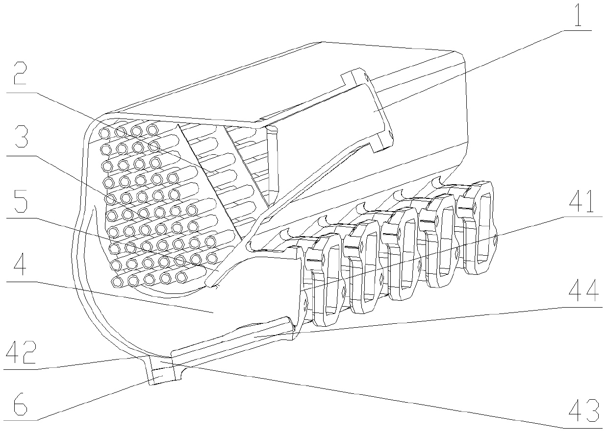
The invention discloses an intercooling inlet pipe of a supercharged engine, which comprises an inlet main pipe and an inlet branch pipe communicated with the inlet main pipe. The bottom of the inlet branch pipe is provided with a bypass hole, and the bypass hole is communicated with the inlet branch pipe and an air cylinder of the supercharged engine. Compared with the prior art, the intercooling inlet pipe modifies a structure of the inlet branch pipe, the bypass hole communicated with the inlet branch pipe and the air cylinder are arranged at the bottom of the inlet branch pipe so that when gas flows into the air cylinder through the bypass hole, the differential pressure caused by the Venturi effect enables condensed water located at the bottommost end of the inlet branch pipe to be sucked into the air cylinder to be combusted, and the problem of accumulation of the condensed water is effectively solved. The invention further discloses the supercharged engine comprising the intercooling inlet pipe.

Description

technical field [0001] The invention relates to the technical field of engines, in particular to an intercooling intake pipe of a supercharged engine. The present invention also relates to a supercharged engine comprising the above-mentioned intercooled intake pipe. Background technique [0002] For a supercharged engine, the intercooler is an important component of the supercharging system. The intercooler is arranged between the supercharger and the engine intake pipe to reduce the intake air temperature of the engine. [0003] The temperature of the exhaust gas discharged from the engine is very high, the heat conduction through the supercharger will increase the temperature of the intake air, and the density of the air will increase during the process of being compressed, which will inevitably lead to an increase in the temperature of the air, thus affecting the charging of the engine Efficiency, which in turn affects the power of the engine, so if you want to further ...

Claims


Application Information

Patent Timeline
IPC IPC(8): F02B29/04
CPCY02T10/146Y02T10/12
Inventor 张英张纪元张华美
Owner WEICHAI POWER CO LTD
Learn More