Single-return-stroke WNS-structure boiler

A technology for boilers and furnaces, applied in the field of single-pass WNS structure boilers, which can solve problems such as easy flue gas leakage from high-temperature moving parts, increased pollutant NOx emissions, and high flame center temperature, so as to improve ignition conditions, reduce NOx production, The effect of reducing the temperature of the combustion flame

Inactive Publication Date: 2017-10-03
陈黎
View PDF5 Cites 0 Cited by
  • Summary
  • Abstract
  • Description
  • Claims
  • Application Information

AI Technical Summary

Problems solved by technology

[0006] The flame center temperature of the existing three-pass WNS gas-fired boiler burner is high, pollutant NOx emissions increase, the flue gas returns more, and the flue pipe parts are longer, resulting in large system resistance and high-temperature moving parts are prone to flue gas leakage. There are major security risks;
[0007] On the other hand, the single-pass WNS structure boiler proposed by the present invention can also be used to solve the problems existing in the existing three-pass WNS gas-fired boilers: many parts, complex structure, cumbersome manufacturing process, and relatively high manufacturing costs.

Method used


Image

  • Single-return-stroke WNS-structure boiler
  • Single-return-stroke WNS-structure boiler
  • Single-return-stroke WNS-structure boiler

Examples


Embodiment 1

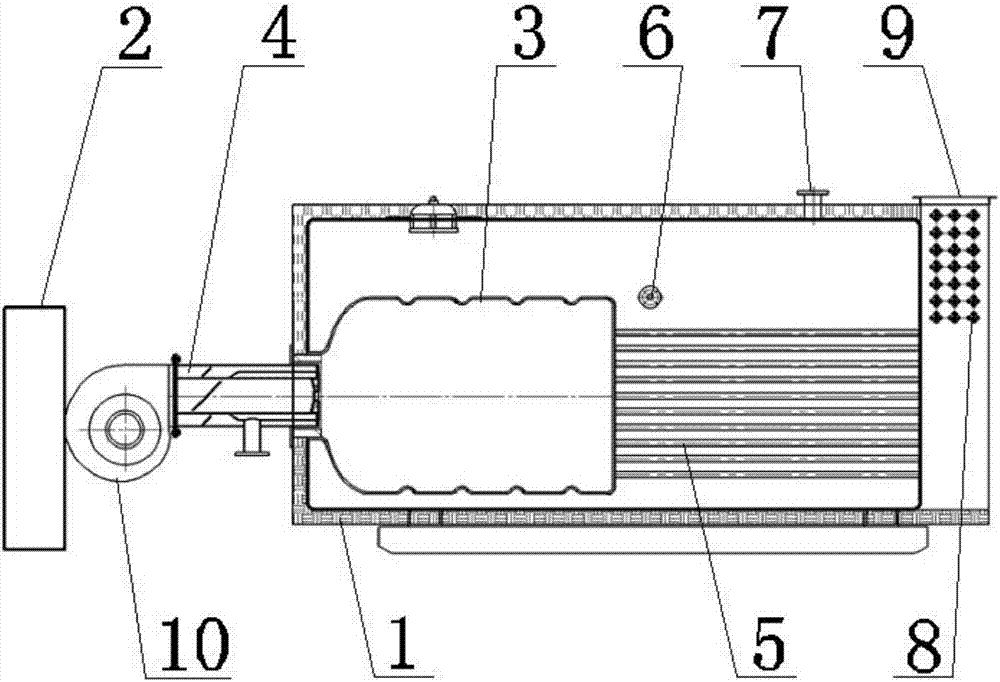
[0031] Such as figure 1 As shown, Embodiment 1 of the present invention provides a single return WNS structure boiler, including: control cabinet 2, burner 4, pot shell 1, corrugated furnace 3, smoke pipe group 5, water inlet 6, hot water or steam outlet 7. The economizer 8 and the flue gas outlet 9, wherein the water inlet 6, the hot water or steam outlet 7 and the flue gas outlet 9 are arranged on the surface of the pot shell 1. The control cabinet 2 controls the operation of the entire boiler, and the boiler can be arranged vertically or horizontally. The burner 4, the corrugated furnace 3 and the smoke pipe group 5 are sequentially connected; among them, the burner 4, the corrugated furnace 3 and the smoke pipe group 5 are connected coaxially in sequence; the burner 4 can be a single-stage fire burner or a double-stage fire burner. Burners, proportional burners, etc., preferably swirl burners here.

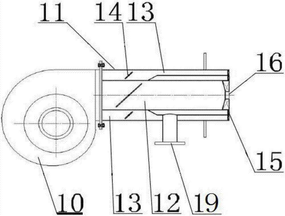
[0032] Such as Figure 2~3 Therefore, the burner 4 includes: a fan 10,...

Embodiment 2

[0040] On the basis of Embodiment 1, based on the above-mentioned structure, a water-cooled burner 23 is arranged around the burner 16, which is used to maintain a certain high temperature, radiate heat, and promote ignition; The rapid rise can reduce the temperature at the burner and protect the 3 walls and the front wall of the corrugated furnace from being damaged by high temperature. But when carrying out the low calorific value fuel combustion of utilization rate lower, the cooling function of water-cooled burner 23 has caused its combustion to hinder, for above-mentioned situation, as Figure 6 As shown, a refractory concrete covering layer 24 can be provided on the water-cooled burner 23 . When the combustion gas burns at the burner 16, under the protection of the refractory concrete covering layer 24, the high temperature at the burner 16 is maintained to radiate heat and promote fuel combustion.


PUM


Abstract

The present invention relates to the technical field of combustion and thermal energy conversion equipment, in particular to a single-return WNS structure boiler, including: a control cabinet, a burner, a pot shell, a corrugated furnace, a smoke pipe group, a water inlet, a hot water or steam outlet, and an economizer And the flue gas outlet, the water inlet, the hot water or steam outlet and the flue gas outlet are arranged on the surface of the pot shell. The burner, corrugated hearth and smoke pipe group are coaxially connected in sequence; the gas inlet is connected to the gas nozzle through the delivery pipe; a burner is arranged around the burner, and the burner is arranged at the other end of the installation pipe. The corrugated furnace and the smoke pipe group are installed in the pot shell to form a single-return structure; there is a flue gas outlet at the top of the tail of the pot shell, and an economizer is arranged between the flue gas outlet and the smoke pipe group. The invention saves the flue gas diverting parts, and adopts a single-return structure. The economizer is installed in the pot shell, and the structure is more compact, which is convenient for installation and transportation; efficiency, saving electricity.

Description

technical field [0001] The invention relates to the technical field of combustion and thermal energy conversion equipment, in particular to a single-pass WNS structure boiler. Background technique [0002] With the development of economy and modern science and technology, gas-fired boilers have become the first choice for boiler combustion raw materials due to their high combustion efficiency, convenient transportation, simple operation, and meeting the requirements of sustainable development and environmental protection. One type of boiler is used by most gas-fired boilers due to its compact structure, small size, high degree of automation, easy installation, safe and reliable operation, etc., with a good development trend and high market demand. [0003] Most of the existing WNS gas boilers on the market adopt a three-circuit structure, using a high-speed direct-flow burner, and adding high-temperature moving parts such as a combustion chamber and a front smoke box. Howeve...

Claims


Application Information

Patent Timeline
Patent Type & Authority Applications(China)
IPC IPC(8): F22B31/00F23C5/32F23C9/00
CPCF22B31/00F23C5/32F23C9/00
Inventor 陈黎文午琪
Owner 陈黎
Why Eureka
Try Eureka