Backlight module

A backlight module and backplane technology, applied in the field of backlight modules, can solve problems such as uneven brightness at the edge of the backlight module, abrasion of the light guide plate, cracking of the light guide plate, etc., to ensure the intensity of light and the uniformity of light, Avoid the effect of changing the light path and avoiding extrusion deformation

Inactive Publication Date: 2012-07-25
SHENZHEN CHINA STAR OPTOELECTRONICS TECH CO LTD
View PDF8 Cites 25 Cited by
  • Summary
  • Abstract
  • Description
  • Claims
  • Application Information

AI Technical Summary

Problems solved by technology

However, in recent years, LCDs have gradually evolved towards thinner and larger sizes, resulting in thinner and thinner light guide plates, which makes the heat absorption and expansion characteristics of the light guide plate stand out, which makes it necessary to install the positioning part of the light guide plate and the back plate when fixing the light guide plate. The locking structure of the light guide plate reserves the gap required for the expansion and contraction of the light guide plate when mating, and then presets a certain amount of movement for the light guide plate inside the backlight module, and the movement of the light guide plate may easily cause the light guide plate to be scratched, etc. problem; at the same time, due to the presence of grooves or raised structures on the light guide plate, the processing cost increases and the mechanical strength of the light guide plate itself is weakened. There are grooves or raised structures around the light plate, which changes the local optical path on the side of the light guide plate, and is prone to optical problems such as uneven brightness at the edge of the backlight module, which greatly reduces the yield of the narrow frame backlight module

Method used


Image

  • Backlight module
  • Backlight module
  • Backlight module

Examples


Embodiment Construction

[0023] In order to further illustrate the technical means adopted by the present invention and its effects, the following describes in detail in conjunction with preferred embodiments of the present invention and accompanying drawings.

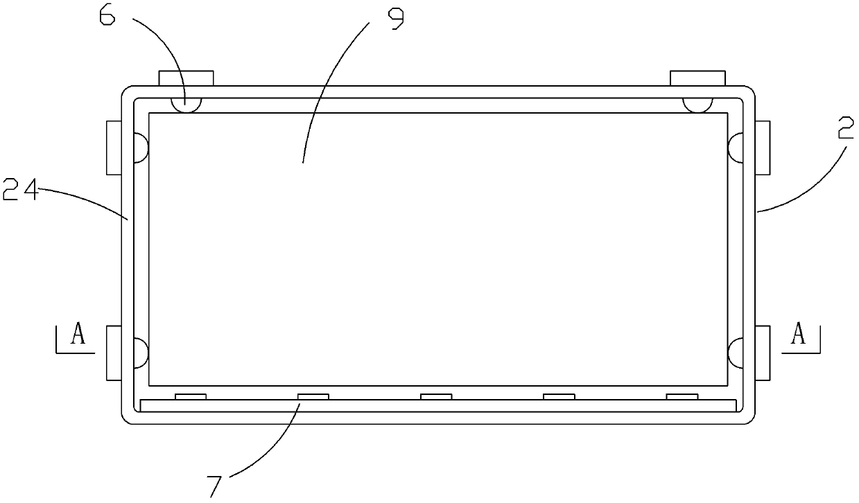
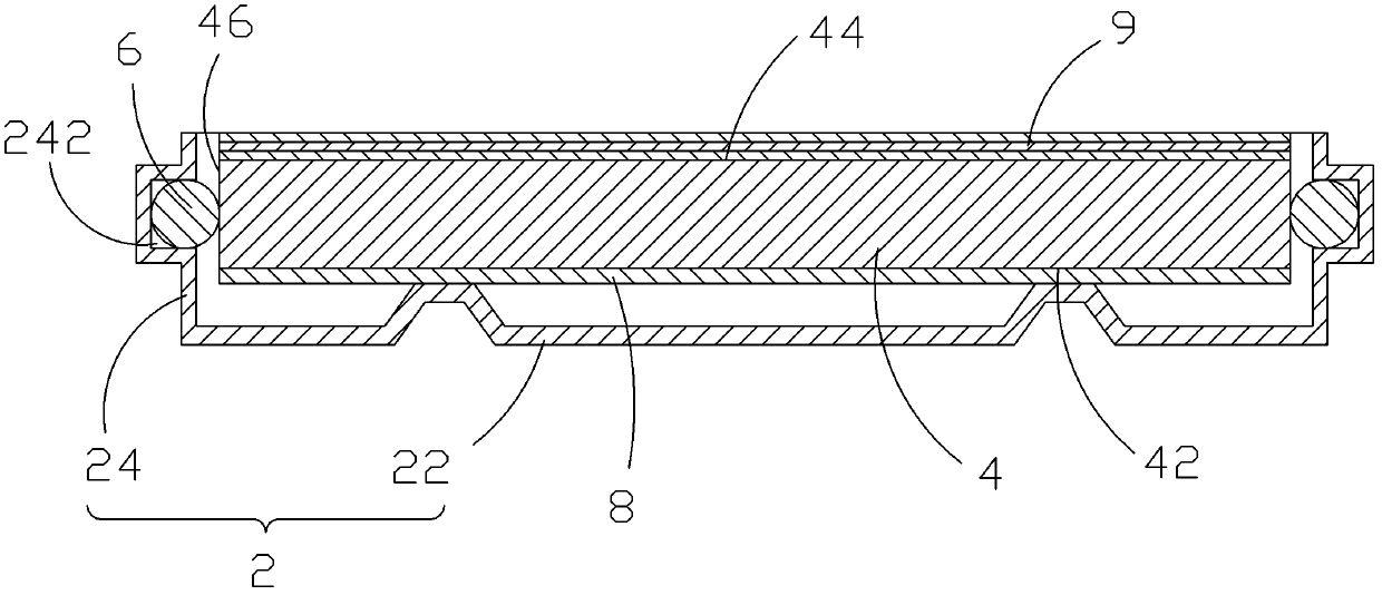
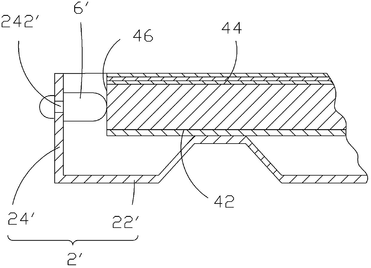
[0024] see figure 1 and figure 2 , as an embodiment of the backlight module of the present invention, the backlight module includes: a backplane 2, a light guide plate 4 disposed inside the backplane 2, and several elastic bodies 6 disposed between the backplane 2 and the light guide plate 4 . The backboard 2 includes a bottom board 22 and a plurality of side boards 24 vertically connected around the bottom board 22 . The light guide plate 4 includes a bottom surface 42 facing the bottom plate, a top surface 44 away from the bottom plate, and several side surfaces 46 connected between the bottom surface 42 and the top surface 44, and the several side surfaces 46 correspond to several sides facing the backplane 2. Side panels 24. Wherein, ...


PUM


Abstract

The invention provides a backlight module. The backlight module comprises a back plate, a light guide plate arranged in the back plate, and a plurality of elastic bodies mounted on the back plate, wherein the back plate includes a bottom plate, and a plurality of side plates vertically connected at the periphery of the bottom plate; the light guide plate includes a bottom surface facing the bottom plate, a top surface away from the bottom plate, and a plurality of side surfaces connected between the bottom surface and the top surface; the plurality of elastic bodies are respectively mounted on the three side plates of the back plate, and butt against the three side surfaces of the light guide plate; and the contact surface between the elastic bodies and the side surfaces of the light guide plate is an arc-shaped surface or a spherical surface. The backlight module provided by the invention can ensure the mechanical strength of the light guide plate by fixing the light guide plate in the back plate through the elastic bodies between the side plates of the back plate and the light guide plate without processing the periphery of the light guide plate by grooving, embossing and so on, and can supply a certain buffer space to prevent extrusion deformation of the light guide plate due to thermal expansion in the prior art, thereby ensuring the luminous intensity and uniformity and reducing the cost.

Description

technical field [0001] The invention relates to a backlight module, in particular to a backlight module in which a light guide plate is fixed by an elastic body. Background technique [0002] A liquid crystal display (LCD, Liquid Crystal Display) has many advantages such as a thin body, power saving, and no radiation, and has been widely used. Most of the liquid crystal display devices currently on the market are backlight liquid crystal displays, which include a liquid crystal display panel and a backlight module. The working principle of the liquid crystal display panel is to place liquid crystal molecules between two parallel glasses. There are many small vertical and horizontal wires between the two glasses. The direction of the liquid crystal molecules is controlled by electrifying or not, and the light from the backlight module is refracted. Generate screen. Since the liquid crystal display panel itself does not emit light, the light source provided by the backlight ...

Claims


Application Information

Patent Timeline
Patent Type & Authority Applications(China)
IPC IPC(8): F21S8/00F21V15/04F21V17/10F21V8/00
CPCG02F1/1333G02B6/0088G02B6/0091G02F1/133308G02F1/133615G02F1/133317G02F1/133322
Inventor 陈仕祥阙成文
Owner SHENZHEN CHINA STAR OPTOELECTRONICS TECH CO LTD
Why Eureka
Try Eureka