

Method and device for measuring surface shape error of optical element at high precision
A technology of optical components and surface shape error, which is applied in the direction of using optical devices, measuring devices, instruments, etc., can solve the problems of cumbersome calibration of interferometers, high prices, and high requirements for the test environment, and achieve simple, fast and cost-effective testing and calibration processes. cheap effect
- Summary
- Abstract
- Description
- Claims
- Application Information
AI Technical Summary
Problems solved by technology
Method used
Image

Examples
specific Embodiment approach 1
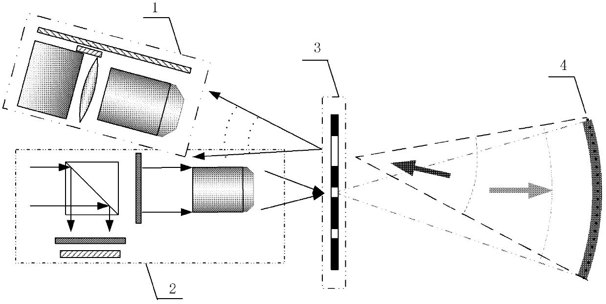
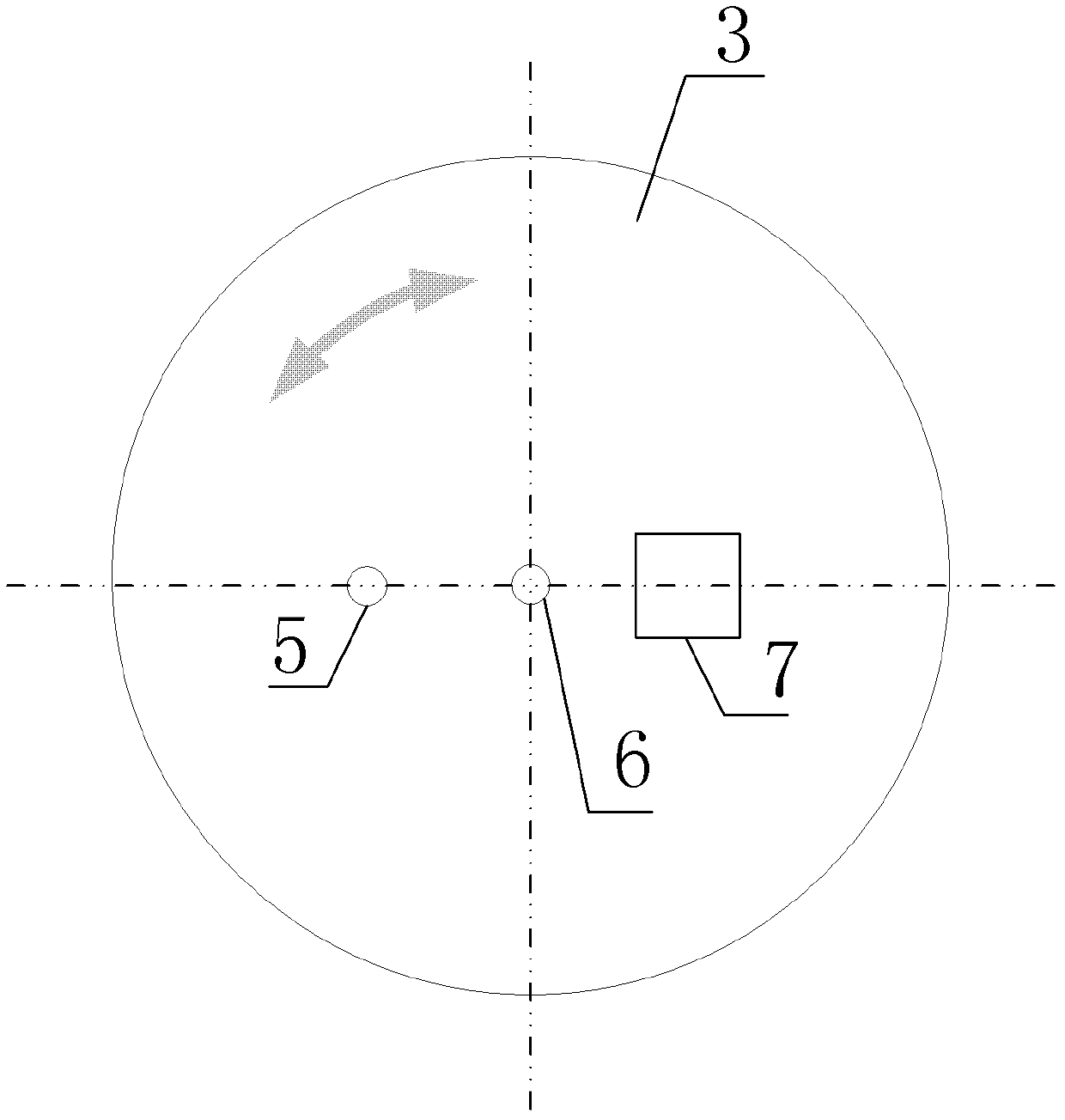
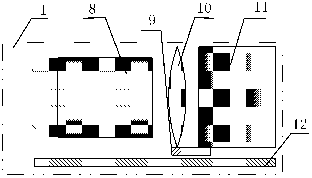
[0016] Specific implementation mode 1. Combination Figure 1 to Figure 4 Describe this embodiment mode, a kind of high-precision testing device of optical element surface shape error described in this embodiment mode, detection device 1, illumination system 2, rotatable small hole plate 3 and optical element 4 to be tested; Small orifice plate 3 is provided with small hole 5, central hole 6 and square hole 7; Rotatable small orifice plate 3 rotates with central hole 6 as the center of circle; The distances of the holes 6 are equal, and the diameters of the central holes 6 are respectively λ / 2NA, wherein NA is the numerical aperture of the optical element to be measured; λ is the wavelength of the light beam emitted by the illumination system 2; the light beam emitted by the illumination system 2 passes through the rotatable The central hole 6 of the small hole plate 3 produces an ideal test beam, which is collected by the detection device 1 after being reflected and converged ...
specific Embodiment approach 2
[0020] Specific embodiment 2. A high-precision testing method for the surface shape of an optical element, the method is realized by the following steps:
[0021] Step A, building a detection platform for the optical imaging system;
[0022] Step B, align the detection device 1 in the detection platform described in step one with the small hole 5 on the rotatable small hole plate 3, and move the precision axial fine-tuning guide rail 9 in the detection device 1 back and forth to obtain 5 different out-of-focus star point images of diffraction;
[0023] Step C, calculating the optical wavefront error of the detection device 1;
[0024] Step D, align the detection device 1 in the detection platform described in step one with the larger square hole 7 on the rotatable small orifice plate 3, and move the precision axial fine-tuning guide rail 9 in the detection device 1 back and forth, so that Obtain different out-of-focus star point images passing through the square hole 7;
[...
PUM
 Abstract
Description
Claims
Application Information