Photovoltaic array combiner box

A photovoltaic array and combiner box technology, applied in the field of photovoltaic power generation, can solve the problems that the output power of the input branch cannot reach the maximum, the maximum power point is different, etc., to simplify the thermal structure design and device selection, reduce heat loss, and improve The effect of overall efficiency

Inactive Publication Date: 2012-07-25
TBEA SUNOASIS +1
View PDF8 Cites 19 Cited by
  • Summary
  • Abstract
  • Description
  • Claims
  • Application Information

AI Technical Summary

Problems solved by technology

[0007] The technical problem to be solved by the present invention is to provide a photovoltaic array combiner box for the above-mentioned defects in the prior art. The branches can still output at the maximum power after

Method used


Image

  • Photovoltaic array combiner box
  • Photovoltaic array combiner box
  • Photovoltaic array combiner box

Examples


Example Embodiment

[0040] Example 1:

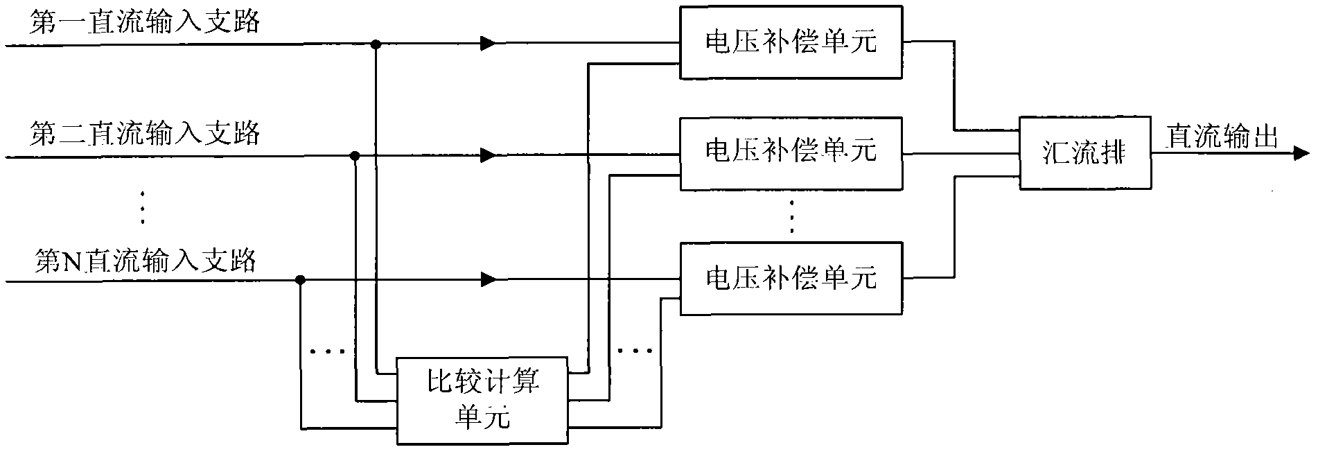
[0041] Such as figure 1 As shown, the photovoltaic array combiner box includes multiple DC input branches, multiple voltage compensation units, and a comparison calculation unit. Wherein, each of the DC input branches has a maximum power tracking function. Here, the DC input branch has a maximum power tracking function, which can be realized by adding DC / DC boost modules to each input branch of the photovoltaic array combiner box. Of course, other ones that can achieve maximum power tracking can also be used. Functional modules are implemented.
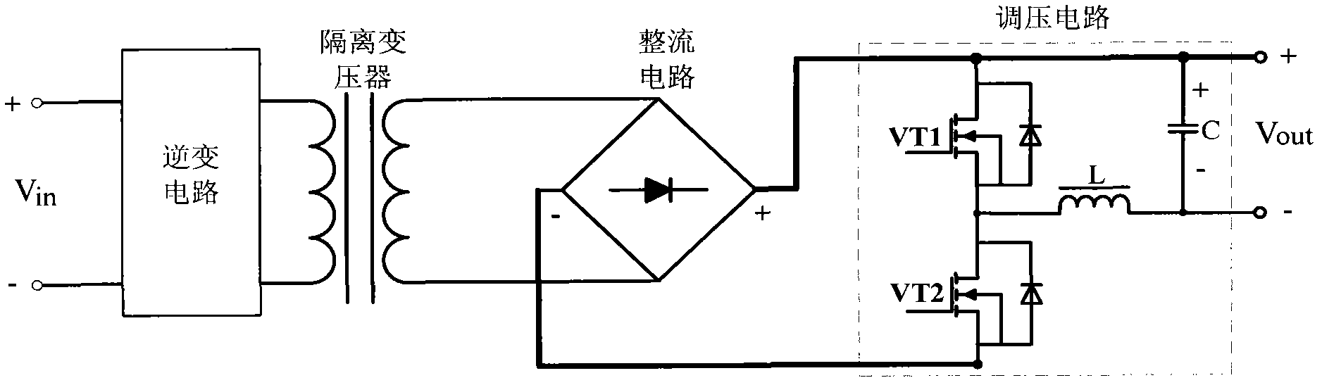
[0042] After the multiple DC input branches are connected in parallel, they are combined into one DC output. The multiple DC input branches may be connected in parallel and combined into one by a bus bar. Preferably, the bus bars are copper bus bars. The positive and negative poles of the input end of each DC input branch are respectively connected to the positive and negative poles of the output end of a photovoltaic...

Example Embodiment

[0064] Example 2:

[0065] The difference between this embodiment and embodiment 1 is:

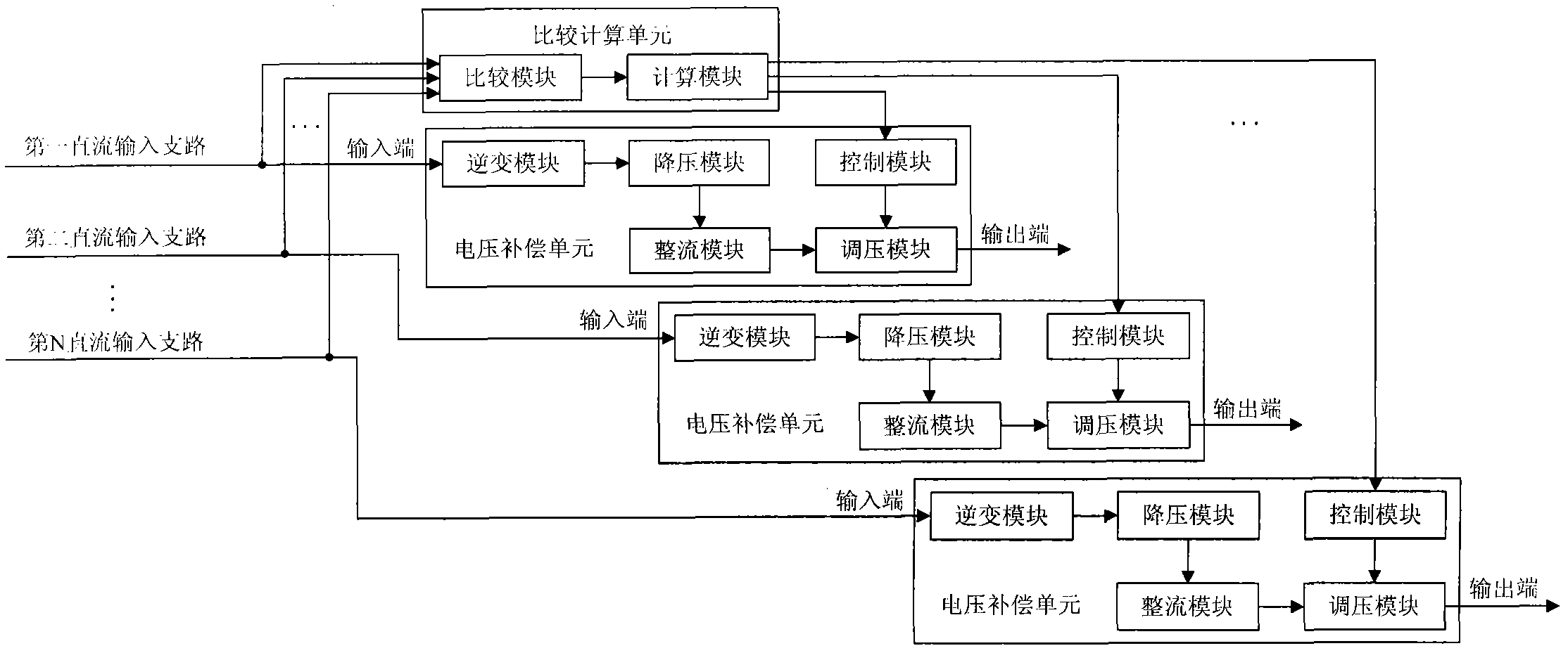
[0066] In this embodiment, the voltage compensation unit does not include an inverter module, a step-down module, and a rectifier module, that is, the voltage compensation unit only includes a control module and a voltage regulation module.

[0067] The other structures and functions in this embodiment are the same as those in Embodiment 1, and will not be repeated here.


PUM


Abstract

The invention provides a photovoltaic array combiner box which comprises multiple DC (direct current) input branches, wherein the multiple DC input branches are connected in parallel and then combined into one DC output; and each branch has a maximum power tracking function so as to work at respective maximum power point. The combiner box also comprises multiple voltage compensation units connected in series with the branches respectively, and a comparison calculation unit, wherein the comparison calculation unit is used for comparing to obtain the maximum value of voltage at the maximum power point of each branch, calculating the difference between the maximum value and the voltage value at each maximum power point respectively, and outputting the difference to the voltage compensation unit corresponding to each branch respectively; and the voltage compensation unit is used for performing voltage compensation for the corresponding branch according to the difference so that the output voltage of the branch is equal to the maximum value. The photovoltaic array combiner box provided by the invention can ensure that each branch still can output voltage at respective maximum power after the output is combined, thus the total output power of the combiner box reaches the maximum.

Description

technical field [0001] The invention belongs to the technical field of photovoltaic power generation, and in particular relates to a photovoltaic array combiner box. Background technique [0002] With the large-scale rise of photovoltaic grid-connected power generation technology, for large-scale photovoltaic grid-connected power generation systems, in order to reduce the connection lines between photovoltaic modules (solar cells) and grid-connected inverters and facilitate maintenance, it is necessary to install photovoltaic modules A photovoltaic array DC confluence device (ie photovoltaic array combiner box) is added between the grid-connected inverter. The converging direct current is converted into alternating current and then transmitted to the power transmission network. [0003] In order to improve the overall efficiency of the photovoltaic grid-connected power generation system, the existing photovoltaic grid-connected inverters generally have a maximum power track...

Claims


Application Information

Patent Timeline
IPC IPC(8): H02N6/00H02J1/10H02S40/30
CPCY02E10/50
Inventor 张新涛刘伟增羊睦汉
Owner TBEA SUNOASIS
Why Eureka
Try Eureka