Chemical mechanical polishing conditioner

A chemical mechanical and dresser technology, applied in the field of CMP dresser, can solve problems such as uneven surface of polishing pad, reduced ability to polish wafers, and reduced CMP treatment effect

Inactive Publication Date: 2012-07-25
SAINT GOBAIN ABRASIVES INC +1
View PDF4 Cites 5 Cited by
  • Summary
  • Abstract
  • Description
  • Claims
  • Application Information

AI Technical Summary

Problems solved by technology

However, after prolonged use, these pores can become worn or become clogged with polishing residue, resulting in an uneven surface of the polishing pad
As a res

Method used


Image

  • Chemical mechanical polishing conditioner
  • Chemical mechanical polishing conditioner
  • Chemical mechanical polishing conditioner

Examples


Embodiment Construction

[0017] In one embodiment, a chemical mechanical polishing (CMP) conditioner may include a substrate. The substrate may comprise a metal and metal alloys including: tungsten, molybdenum, zirconium, copper, nickel, stainless steel, or the like. Alternatively, the substrate may comprise a ceramic, such as oxides, carbides, nitrides, oxynitrides, suicides, borides, or any combination thereof. Examples include: Al 2 o 3 , SiC, WC, Si 3 N 4 , ZrO 2 、Cr 2 N 3 , and the like. Preferably, the substrate is selected to resist corrosion from the CMP environment. The substrate may have a thickness of between about 2 mm and about 15 mm.

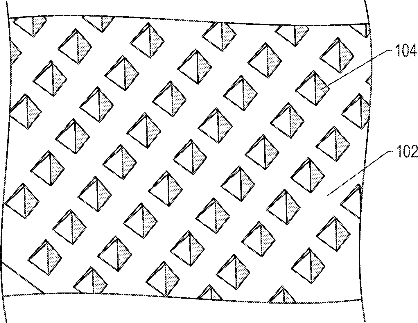
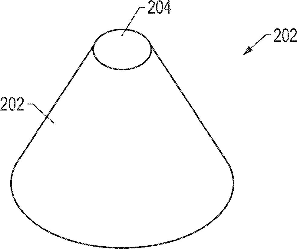
[0018] A surface of the substrate may include a plurality of microscopic protrusions. figure 1 An example of a surface 102 with a plurality of micro-protrusions 104 is shown. These microprotrusions may be formed of the same material as the base. In addition, the micro-protrusions may be continuous with the base and have no boundaries between th...


PUM

PropertyMeasurementUnit
Heightaaaaaaaaaa
The average thicknessaaaaaaaaaa

Abstract

A chemical mechanical polishing (CMP) conditioner includes a ceramic substrate having a major surface, and an abrasive coating overlying the major surface. The major surface can include micro-protrusions arranged in a curved pattern. Alternatively, the micro-protrusions can be arranged in an irregular pattern.

Description

technical field [0001] The present disclosure relates generally to chemical mechanical polishing (CMP) conditioners, and more particularly to a ceramic substrate based CMP conditioner. Background technique [0002] Chemical mechanical polishing is widely used in the manufacture of semiconductor devices in order to obtain smooth and planar wafer surfaces. Typically, the wafer to be polished is held by a support that is positioned on a polishing pad attached on a rotating table. By applying slurry to the pad and applying pressure to the support, the wafer is polished by the relative movement of the table and support. A conventional polishing pad used in a chemical mechanical polishing process generally includes pores having a diameter not greater than 200 micrometers. When pressure is applied to the polishing pad, these pores can exhibit a pumping effect to achieve high removal rates. However, after prolonged use, these pores may become worn or clogged with polishing residu...

Claims


Application Information

Patent Timeline
IPC IPC(8): H01L21/304
CPCB24B53/007B24D3/14
Inventor J·吴R·W·J·霍尔E·M·舒勒S·拉曼斯
Owner SAINT GOBAIN ABRASIVES INC
Why Eureka
Try Eureka