Soil screw traction self-traveling type tunnel piercing device and piercing method

A tunneling, self-propelled technology, applied in tunnels, earth-moving drilling, mining equipment, etc., can solve problems such as application

Active Publication Date: 2012-08-01
BEIJING UNIV OF TECH
View PDF4 Cites 9 Cited by
  • Summary
  • Abstract
  • Description
  • Claims
  • Application Information

AI Technical Summary

Problems solved by technology

[0003] In order to solve the problem that in the process of soil construction, it is necessary to apply reaction pressure to the artificial structure behind the excavation d

Method used


Image

  • Soil screw traction self-traveling type tunnel piercing device and piercing method
  • Soil screw traction self-traveling type tunnel piercing device and piercing method
  • Soil screw traction self-traveling type tunnel piercing device and piercing method

Examples


Embodiment 1

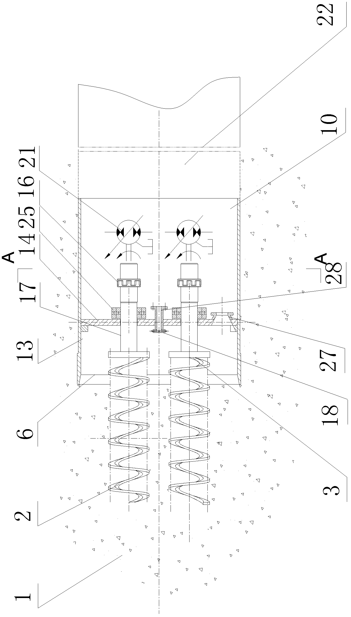
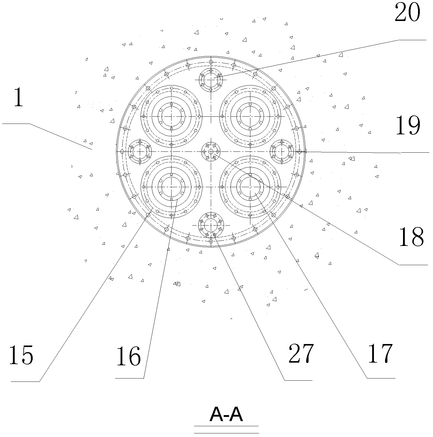
[0031] like figure 1 As shown: one or more spiral pullers 2 are installed at the front end of the first section 10 of the roadheader, through the spiral connecting disc 3 connected with the 2, and then through the spiral puller shaft 17, connected with the coupling 16, the joint The shaft device 16 is connected with the torque driving source 21, and under the action of the torque provided by 21, it drives the screw puller 2 to rotate in the soil body 1 in front of the working face, and the rotation of the screw puller 2 in the soil body 1 generates The pulling axial force in front of the working face of the roadheader, the pulling axial force is transmitted to the thrust bearing 25 through the helical pulling shaft 17, pushing the partition plate 14 solidly connected with the first section 10 of the roadheader to move forward, thereby driving the second One section 10 moves forward, completes the forward movement of the first section 10 of the roadheader. The soil body 1 in f...

Embodiment 2

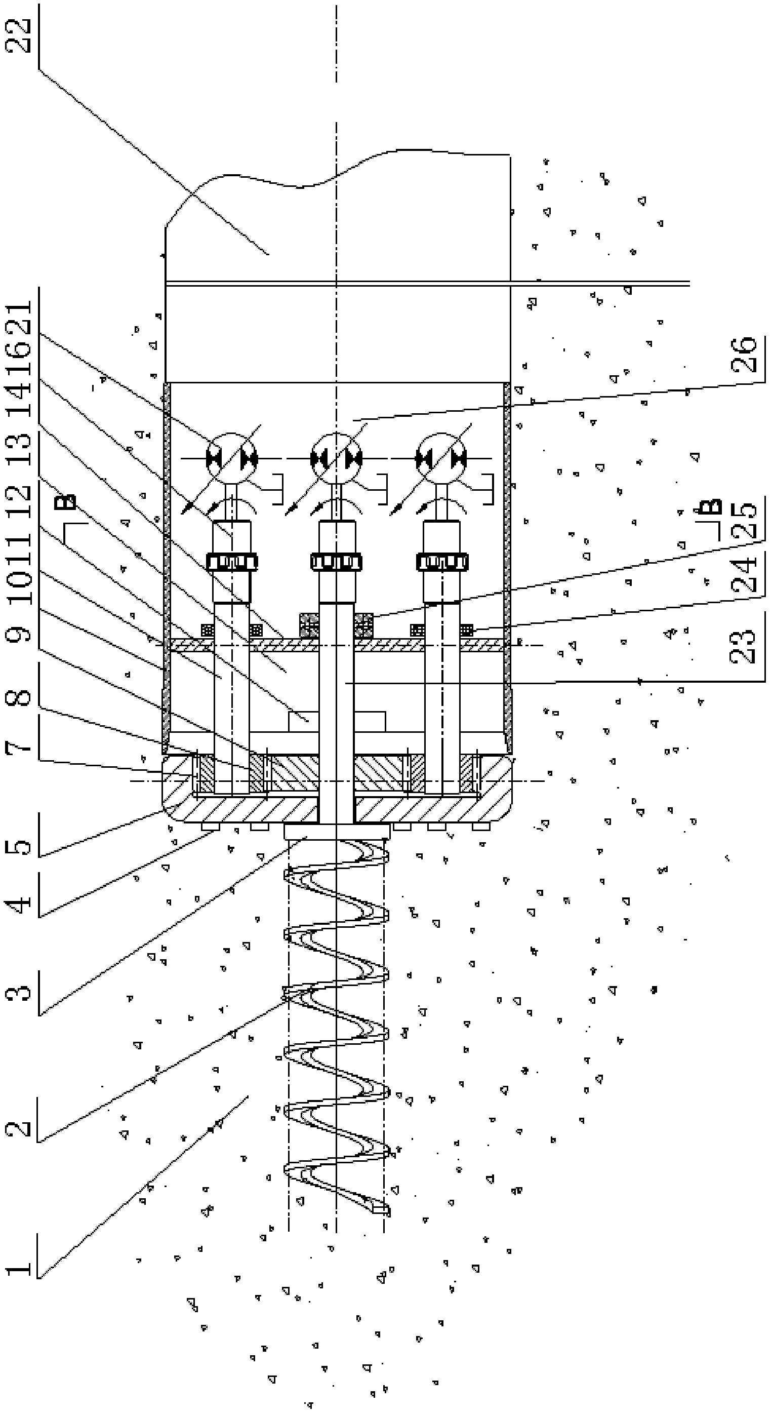
[0033] like figure 2 As shown, a cutting cutter head 5 is installed at the front end of the first section of the casing 10 of the roadheader. The cutting tool 4 for cutting the soil body 1 is installed on the cutting cutter head 5. The transmission meshing teeth 7 on the cutting cutter head 5 are meshed with it. The cutter head drive gear 8 is driven, and the cutter head drive gear 8 is connected to the torque drive source 21 through the bearing 24, the cutter head drive shaft 11, and the shaft coupling 16, so as to drive the cutting tool 4 on the cutting cutter head 5 to cut the soil body 1. The leading helical puller 2 protruding into the soil 1 is connected to the torque drive source 21 located in the working room 26 behind the roadheader through the leading helical puller shaft 23 through the helical connecting disc 3 connected to it. Driven by the torque drive source 21, the leading helical puller 2 rotates in the soil body 1, acts on the partition plate 14 through the t...

Embodiment 3

[0035] like image 3As shown, a cutting cutterhead 5 is installed at the front end of the roadheader housing 10, and a cutting tool 4 for cutting the soil body 1 is installed on the cutting cutterhead 5. The driving wheel 9 is driven, the cutter head driving gear 9 is connected with the torque driving source 21 arranged in the working room 26 of the front section of the roadheader through the central shaft 23, and the shaft coupling 16. Under the action of the rotation of the torque drive source 21, through the coupling 16, the central shaft 23, the helical connecting disc 3 drives the leading helical puller 2 to rotate and screw into the soil body 1, and the pulling drive shaft 23 acts on the soil bin partition 14 On the thrust bearing 25 on the top, the boring machine casing 10 is moved forward. While driving the central shaft 23 to rotate, the cutter head drive gear 9 drives the cutting cutter head 5 to rotate through the cutter head drive gear 8, so that the cutting tool ...


PUM


Abstract

A soil screw traction self-traveling type tunnel piercing device and a piercing method belong to the field of trenchless underground tunnel or pipe construction. The soil screw traction self-traveling type tunnel piercing device comprises more than one barrel, and the barrels are connected mutually. More than one screw structure is fixed on the first barrel along the axis of the barrel, the screw structures rotate around self axial centers, and free ends for excavating extend into soil in front of the piercing device. The screw structures are connected with a power driving source. In a piercing process, movement of the screw structures is controlled so as to realize piercing and turning. By the aid of the device and the method, thrust to the front of a total working face is comprehensively and integrally increased, and the advanced piercing technology which relies on a rear artificial structure but does not relies on the prior art is formed.

Description

technical field [0001] The invention relates to a tunneling device and a tunneling method, which provides a new self-propelled tunneling device and method for the construction technology of underground tunnels, and provides technical support for more fully developing and utilizing underground spaces. Excavation of underground tunnel or pipeline construction field. Background technique [0002] At present, the shield tunneling construction method and the pipe jacking construction method widely used in the construction of underground works need to apply reaction pressure to the artificial structures behind the tunneling device to move forward. This acting pressure is the temporary load of the construction on the artificial structure. As a result, the thickness of the structure of the artificial structure increases. Under the condition that the inner space of the tunnel guarantees the function, the tunnel excavation diameter is increased, resulting in an increase in the amount ...

Claims


Application Information

Patent Timeline
IPC IPC(8): E21D9/08E21D9/12
Inventor 卢清国
Owner BEIJING UNIV OF TECH
Why Eureka
Try Eureka