Constant-pressure water-gas compatible cabin power energy storage system

A power energy storage system, water gas technology, applied in the field of power energy storage system using water-gas co-containment cabin, can solve the problem of high cost

Active Publication Date: 2012-08-01
王焕然
View PDF7 Cites 44 Cited by
  • Summary
  • Abstract
  • Description
  • Claims
  • Application Information

AI Technical Summary

Problems solved by technology

[0009] Aiming at the defects of high equipment cost of the existing compressed air energy storage power station and the special geographical environment required by the pumped storage power station, the purpose of the present invention is to provide an improved electric energy storage system with water-gas co-containment cabin, which can not only reduce the The cost of energy storage can improve the energy conversion efficiency of the energy storage device, and it can solve the problem of stable pressure in the water-gas coexistence cabin during the power generation process of the system

Method used


Image

  • Constant-pressure water-gas compatible cabin power energy storage system
  • Constant-pressure water-gas compatible cabin power energy storage system
  • Constant-pressure water-gas compatible cabin power energy storage system

Examples


Embodiment Construction

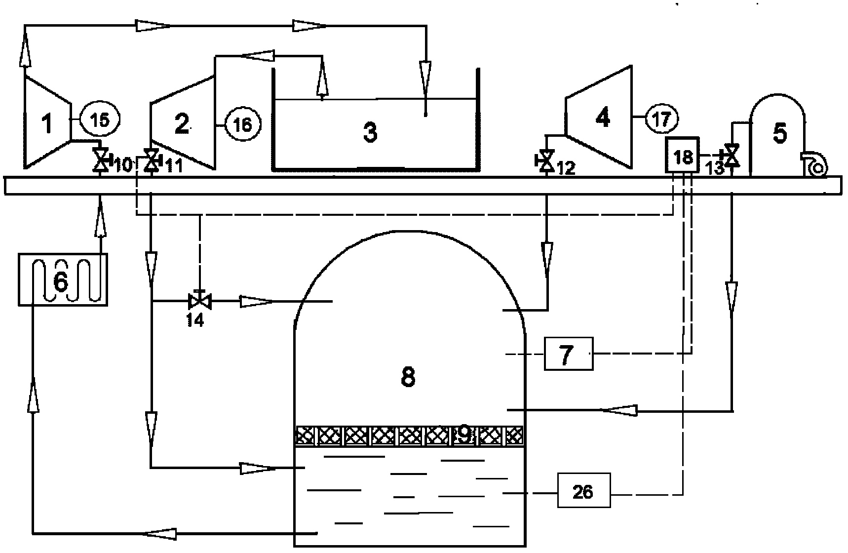
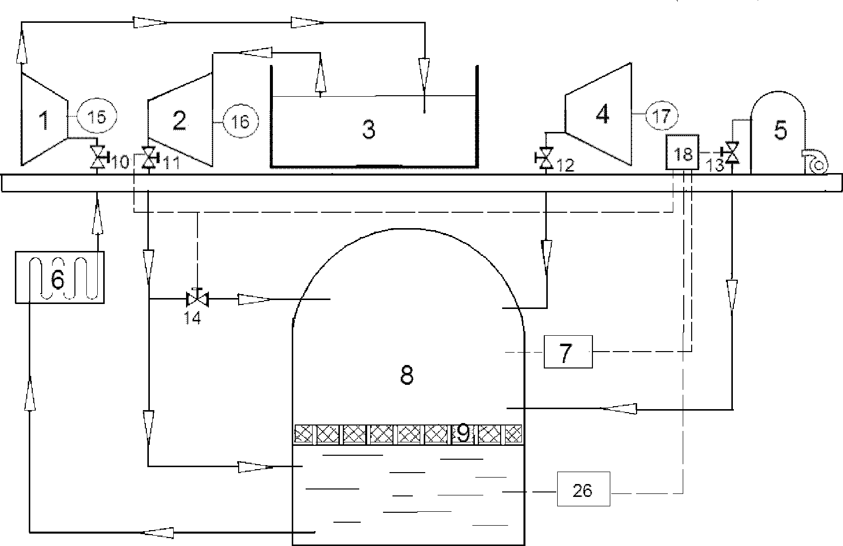
[0025] Such as figure 1 As shown, the constant pressure water-gas co-containment cabin power energy storage system of the present invention includes a gas compressor unit 4 driven by a compressor motor 17, a water pump unit 2 driven by a water pump motor 16, a water storage tank 3 connected to the atmosphere above and The water turbine 1 that can drive the generator 15 to generate electricity. The outlet of the water turbine 1 provides water for the storage tank through the pipeline. The water pump unit 2 pumps water from the water storage tank through the pipeline. The outlet of the gas compressor unit 4 passes through the valve 12 and the pipeline. The upper part of the co-containment cabin 8 is connected; the outlet of the water pump unit 2 is connected to the lower part of the water-gas co-containment cabin through a pipeline through the valve 11, and the other is connected to the upper part of the water-gas co-containment cabin through the smart valve 14 and the spray pipe...


PUM


Abstract

The invention discloses a constant-pressure water-gas compatible cabin power energy storage system. The power energy storage system comprises a water-gas compatible cabin, a gas compressor unit, a water pump unit, a water reservoir and a water turbine, wherein a water draining port of the water turbine is used for providing ingoing water for the water reservoir; the water pump unit is used for pumping water from the water reservoir through a pipeline; an outlet of the gas compression unit is communicated with the water-gas compatible cabin through a valve and a pipeline; an outlet of the water-gas compatible cabin is communicated with the water turbine through a pipeline and a valve; and the water turbine drags a generator to generate power and output power energy. The power energy storage system is characterized by further comprising a steam boiler which is connected with the water-gas compatible cabin through a first intelligent valve and a steam conveying pipeline; one path of an outlet of the water pump unit is communicated with the lower part of the water-gas compatible cabin through a third intelligent valve and a pipeline; another path of the outlet of the water pump unit is communicated with the upper part of the water-gas compatible cabin through a second intelligent valve and a spraying pipe; and the three intelligent valves are controlled by a gas pressure stability control device.

Description

technical field [0001] The invention relates to a system for physical energy storage of electric energy, in particular to a system for realizing electric energy storage by utilizing a water-air coexistence chamber. Background technique [0002] Since last year, China has surpassed the United States to become the world's largest energy consumer. In the future, with China's rapid development, energy consumption will increase significantly. my country will bear more and more burdens in energy consumption, energy conservation and emission reduction Greater international pressure. [0003] At present, the mainstream trend of world energy development is undergoing major changes, and is gradually moving towards the road of abandoning nuclear power and hydropower. For example, Germany, the core country in Europe, has announced that it will abandon nuclear power in 2020, and other European countries have blown up expired hydropower stations; With energy utilization, gradually increas...

Claims


Application Information

Patent Timeline
Patent Type & Authority Applications(China)
IPC IPC(8): F03B13/06
CPCY02E60/17Y02E10/22Y02E10/20Y02E60/16
Inventor 王焕然
Owner 王焕然
Why Eureka
Try Eureka