Evaporative and electronic double refrigeration cooling fan

An electronic refrigeration and cooling fan technology, which is applied in space heating and ventilation, household heating, lighting and heating equipment, etc., can solve problems such as rising room temperature, low evaporation efficiency and low heat exchange efficiency, and affecting the effect of cooling and cooling , to achieve an obvious cooling effect

Inactive Publication Date: 2012-08-01
GD MIDEA ENVIRONMENT APPLIANCES MFG +1
View PDF7 Cites 7 Cited by
  • Summary
  • Abstract
  • Description
  • Claims
  • Application Information

AI Technical Summary

Problems solved by technology

[0005] However, due to the large amount of circulating water in this scheme, and the poor insulation effect of the water tank and the water inlet and outlet pipes, the cooling capacity of the cold water in the water tank and the water inlet and outlet pipes will lose a lot, so the temperature of the circulating water cannot drop much
According to the principle of evaporative refrigeration, the cooling effect of evaporative cooling is determined by the evaporation of circulating water, and the cooling effect of evaporative cooling is not significantly improved by a small decrease in circulating water temperature. It is difficult to achieve the ideal cooling and cooling effect only by relying on a single cooling of evaporative cooling
[0006] In addition, the evaporative refrigeration device in this scheme still adopts the method of rolling curtains, the evaporation efficiency of the circulating water on it and the heat exchange efficiency with the air are low, and the cooling and cooling effect is not obvious
[0007] In addition, the electronic refrigeration device also generates a certain amount of heat while cooling. In the above-mentioned patent, the waste heat generated by the electronic refrigeration device is directly discharged into the room through the cooling fan, which will cause the room temperature to rise, which will also affect its cooling. Effect

Method used


Image

  • Evaporative and electronic double refrigeration cooling fan
  • Evaporative and electronic double refrigeration cooling fan
  • Evaporative and electronic double refrigeration cooling fan

Examples


Embodiment 1

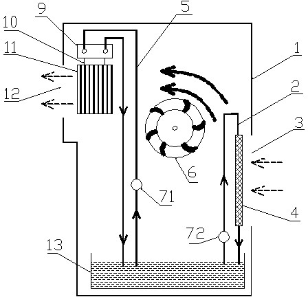
[0024] Such as figure 1 As shown, the present embodiment includes a box body 1 having an air inlet 3 and an air outlet 12, and an electronic refrigeration system and an evaporative refrigeration system in the box body 1, and each of the two refrigeration systems has a set of water circuit circulation devices, as follows:

[0025] The electronic refrigeration system includes an electronic refrigeration chip 10, which has a cold surface and a hot surface. 5 is connected with the heat dissipation heat exchanger 9 and the water storage tank 13, and is used to bring the heat in the heat dissipation exchanger 9 to the water storage tank 13; the self-priming water pump 71 is connected with the water circulation pipe 5, and is used for circulating water Provide power.

[0026] The evaporative refrigeration system includes a humidification filter material 4, the air passing through the humidification filter material 4 will be evaporated and cooled by water, the humidity will increase,...

Embodiment 2

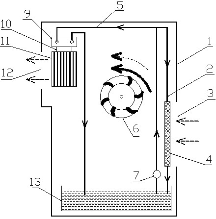
[0030] Such as figure 2 As shown, the difference between this embodiment and Embodiment 1 is that a part of the inlet pipe of the water circuit circulation pipe of the electronic and evaporative refrigeration systems is combined into one to form a shared inlet pipe, and the self-priming water pump 7 Just install on it. Compared with Embodiment 1, this embodiment can not only simplify the circulating water circuit in the cooling fan of the present invention, but also reduce the cost of a self-priming water pump and reduce the cost of the cooling fan of the present invention.

Embodiment 3

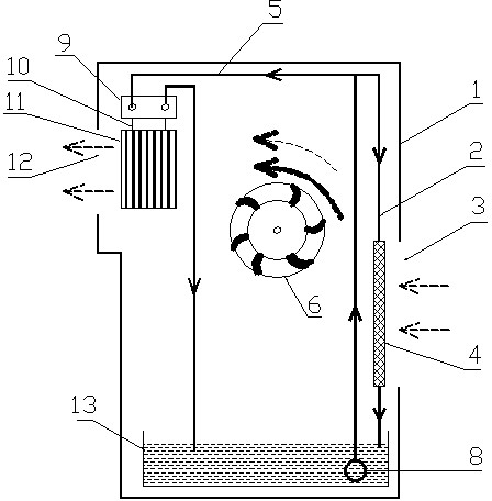
[0032] Such as image 3 As shown, compared with Embodiment 2, the present embodiment replaces the self-priming water pump 7 in Embodiment 2 with a submersible pump 8 . Compared with self-priming water pumps, submersible pumps on the market have more mature technology and relatively lower prices, so this embodiment can further reduce the cost of the cooling fan of the present invention.

[0033] In the above three embodiments provided by the present invention, the refrigeration heat exchanger 11 is located near the air outlet 12, but obviously, the location of the refrigeration heat exchanger 11 is not limited to this, and can also be placed in other locations in the box body 1 , for example, can also be placed between the electric wind wheel 6 and the humidifying filter material 4, as long as the cooling heat exchanger 11 can fully contact the air flowing through the casing 1 for heat exchange.

[0034] Figure 4 It is a structural schematic diagram of an embodiment of the h...


PUM


Abstract

The invention discloses an evaporative and electronic double refrigeration cooling fan, which includes a box body provided with a wind inlet and a wind outlet, as well as an electronic refrigeration system, an evaporative refrigeration system and an electric wind wheel which are placed in the box body, wherein the electronic refrigeration system includes an electronic refrigeration chip provided with a cold surface and a hot surface, a refrigeration heat exchanger connected with the cold surface and used for refrigerating air, a radiating heat exchanger connected with the hot surface and used for exchanging heat with the hot surface, and a water way circulation device connected with the radiating heat exchanger and used for removing heat of the hot surface; and the evaporative refrigeration system includes humidification filtering material and a water way circulation device connected with the humidification filtering material, and the two refrigeration systems are provided with water pumps connected with water way circulation pipes, and share one water storage tank. The evaporative and electronic double refrigeration cooling fan provided by the invention can be used for evaporation and electronic double refrigeration for air in the box body, has high refrigeration efficiency, can be used for self-treatment for waste heat inside the electronic refrigeration system, and effectively improves the cooling effect of the conventional cooling fan.

Description

technical field [0001] The invention relates to a cooling fan, in particular to a cooling fan with double evaporation and electronic refrigeration. Background technique [0002] The existing cooling fans on the market basically use the principle of water evaporation and heat absorption to make the air pass through the humidification filter material, so as to achieve the purpose of cooling and humidifying the air. It is small in size, movable, cheap, energy-saving and environmentally friendly, and has a broad market prospect. However, due to the limitation of the principle of water evaporation and heat absorption, the effect of cooling and cooling is not ideal. [0003] In order to improve the cooling effect, some cooling fans are equipped with ice crystal boxes, which are frozen and put into the cooling fan water tank for use. However, the shell of the ice crystal box is mostly plastic, which has poor thermal conductivity, and the contact area between the ice crystal box an...

Claims


Application Information

Patent Timeline
Patent Type & Authority Applications(China)
IPC IPC(8): F24F5/00
Inventor 豆海高洁艾耀平聂勇
Owner GD MIDEA ENVIRONMENT APPLIANCES MFG
Why Eureka
Try Eureka