Mixed refrigerant circulation natural gas zone pressure liquefaction technology with sublimation removal of CO2

A technology for mixing refrigerant and natural gas, applied in the chemical and low temperature fields, can solve the problems of not involving the natural gas liquefaction process, unable to ensure that natural gas will not be precipitated, difficult to popularize and apply, etc., saving equipment investment, reducing floor space, and energy consumption. reduced effect

Inactive Publication Date: 2012-08-01
SHANGHAI JIAO TONG UNIV
View PDF5 Cites 21 Cited by
  • Summary
  • Abstract
  • Description
  • Claims
  • Application Information

AI Technical Summary

Problems solved by technology

However, the material of the cooler in this patent needs to be one of metal oxide, ceramics, single crystal or sapphire, which is too special and expensive to be popularized and applied; and the solid phase as the core of the patent is in the center of the container rather than on the wall Formed technology, it is difficult to realize in engineering practice
The patent number is 5819555, and the title is "Removal of CO from feed stream through gas-solid separation 2 A method” of the U.S. Patent, which proposes the related desublimation to remove CO 2 technology, but it does not involve the natural gas liquefaction process, and cannot guarantee that the natural gas will not precipitate solid CO in the subsequent liquefaction process 2

Method used


Image

  • Mixed refrigerant circulation natural gas zone pressure liquefaction technology with sublimation removal of CO2
  • Mixed refrigerant circulation natural gas zone pressure liquefaction technology with sublimation removal of CO2

Examples


Embodiment 1

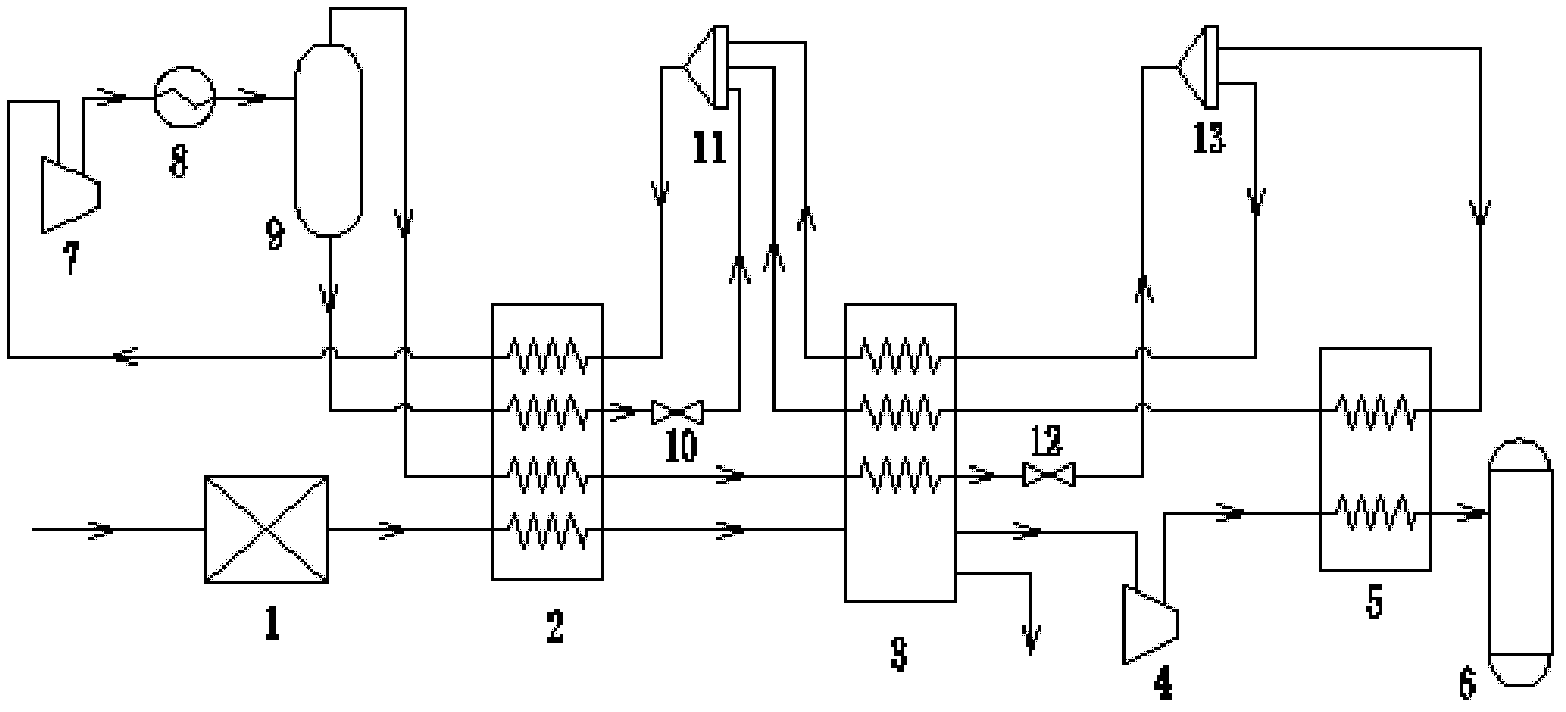
[0031] A CO removal with desublimation 2 The mixed refrigerant cycle natural gas liquefaction process under pressure, the implementation scheme is as follows figure 1 shown. Mixed refrigerant molar composition 37.03% CH 4 +35.63%C 2 h 6 +0.41%C 3 h 8 +12.44% i-C 4 h 10 +10.58% i-C 5 h 12 +3.92%N 2 , The flow rate is 4.5kmol / h, and the molar composition of raw natural gas is 0.5% CO 2 +99.5%CH 4 , pressure 1.5MPa, flow rate 1kmol / h, CO removal with desublimation 2 The specific steps of the mixed refrigerant cycle natural gas liquefaction process under pressure are as follows:

[0032] 1. Since the raw natural gas is within the pressure range of 1.4-1.6MPa, the pressure regulating device 1 is omitted. The raw material gas is introduced into the precooler 2, absorbs cooling energy from the mixed refrigerant, flows out of the precooler 2, and the temperature drops to -40°C;

[0033] 2. The natural gas pre-cooled in step 1 is introduced into the crystallizer 3, and t...

Embodiment 2

[0040] A CO removal with desublimation 2 The mixed refrigerant cycle natural gas liquefaction process under pressure, in the process of natural gas liquefaction to desublimate CO 2 , and then produce LNG products under pressure. The innovative design of the process cancels the CO 2 Pretreatment device, and ensure no CO in the subsequent liquefaction process 2 Crystals precipitated.

[0041] Mixed refrigerant molar composition 36.79% CH 4 +36.19% C 2 h 6 +12.86% i-C 4 h 10 +11.14% i-C 5 h 12 +3.02%N 2 , the flow rate is 4.512kmol / h, and the molar composition of raw natural gas is 10% CO 2 +90%CH 4 , pressure 1.5MPa, flow rate 1kmol / h, CO removal with desublimation 2 The specific steps of the mixed refrigerant cycle natural gas liquefaction process under pressure are as follows:

[0042] 1. Since the raw natural gas is within the pressure range of 1.4-1.6MPa, the pressure regulating device 1 is omitted. The raw material gas is introduced into the precooler 2, absor...

Embodiment 3

[0050] A CO removal with desublimation 2 The mixed refrigerant cycle natural gas liquefaction process under pressure, in the process of natural gas liquefaction to desublimate CO 2 , and then produce LNG products under pressure. The innovative design of the process cancels the CO 2 Pretreatment device, and ensure no CO in the subsequent liquefaction process 2 Crystals precipitated.

[0051] Mixed refrigerant molar composition 26.29% CH 4 +40.08% C 2 h 6 +17.12% i-C 4 h 10 +14.03% i-C 5 h 12 +2.49%N 2 , The flow rate is 4.512kmol / h, and the molar composition of raw natural gas is 30%CO 2 +70%CH 4 , pressure 1.5MPa, flow rate 1kmol / h, CO removal with desublimation 2 The specific steps of the mixed refrigerant cycle natural gas liquefaction process under pressure are as follows:

[0052] 1. Since the raw natural gas is within the pressure range of 1.4-1.6MPa, the pressure regulating device 1 is omitted. The raw material gas is introduced into the precooler 2, absorb...


PUM


Abstract

The invention relates to mixed refrigerant circulation natural gas zone pressure liquefaction technology with sublimation removal of CO2. In the liquefaction process, natural gas maintains a gas state and is pre-cooled, and then enters a crystallizer to be continuously cooled, and the content of CO2 is reduced to 0.5% while solid dry ice is separated through sublimation. Next the natural gas enters a low temperature compressor for pressurization, then enters a liquefaction device, is liquefied under high pressure, and enters a storage tank for storage under. The cold energy required by the liquefaction process is provided by an independent mixed refrigerant circulation refrigeration system. Compared with the prior art, the mixed refrigerant circulation natural gas zone pressure liquefaction technology with sublimation removal of CO2 omits a CO2 pre-treatment device which occupies large area in the conventional natural gas liquefaction process, can greatly reduce investment cost that an offshore platform with high manufacture cost performs natural gas liquefaction, simultaneously, the energy consumption of refrigeration circulation is also reduced by liquefying the natural gas at high temperature.

Description

technical field [0001] The present invention relates to the purification and liquefaction process of natural gas, which is a liquefaction process for removing carbon dioxide at low temperature in the liquefaction process of natural gas, especially a process for desublimation and removal of carbon dioxide in the process of liquefaction of natural gas with pressure in mixed refrigerant cycle (MRC) Liquefaction process. It belongs to the field of chemical industry and low temperature technology. Background technique [0002] Exploration practice has proved that there are abundant oil and gas resources in many sedimentary basins in China's sea area, and the proven offshore natural gas reserves are about 1 / 3 of the national natural gas reserves. The development and utilization of offshore natural gas can not only provide a clean energy with high calorific value, but also reduce the dependence on oil resources, which has important environmental protection and energy strategic sec...

Claims


Application Information

Patent Timeline
Patent Type & Authority Applications(China)
IPC IPC(8): F25J3/08F25J1/02
CPCF25J1/0022F25J1/0055F25J1/0212F25J1/0254F25J2205/20F25J2220/66F25J2230/08F25J2230/30
Inventor 林文胜熊晓俊
Owner SHANGHAI JIAO TONG UNIV
Why Eureka
Try Eureka