Rock soil rheological test equipment

A rheological test, geotechnical technology, applied in the direction of applying stable tension/pressure to test the strength of materials, measuring devices, instruments, etc., can solve the problems of reference value discount, uneconomical, large manpower and financial resources, etc., to achieve reference value Large, improve the application level, the effect of a wide range of applications

Active Publication Date: 2012-08-01
CHINA UNIV OF MINING & TECH (BEIJING)
View PDF3 Cites 16 Cited by
  • Summary
  • Abstract
  • Description
  • Claims
  • Application Information

AI Technical Summary

Problems solved by technology

At present, the rheological test of rock and soil mainly uses a triaxial rheometer, which can exert pressure on the rock and soil in the radial and axial directions, but the radial pressure and the axial pressure interfere with each other, so the axial Pressure and radial pressure cannot be independent
In the actual failure process of rock and soil, rock and soil tension and shear stress are the main reasons for rock and soil damage. During the rock and soil tension process, the axial force is smaller than the radial force, and the current triaxial rheometer It can realize that the axial force of the rock and soil specimen is greater than the radial force, because when the traditional triaxial rheometer is used for the triaxial test, the entire specimen bears the working oil pressure inside the pressure chamber (customarily called hydrostatic pressure) -"Archimedes' Law"), the axial pressure of the specimen includes the pressure inside the pressure chamber in addition to the pressure exerted by the axial loading system. When the pressure of the axial loading system is zero, the axial pressure of the specimen still bears the pres

Method used


Image

  • Rock soil rheological test equipment
  • Rock soil rheological test equipment
  • Rock soil rheological test equipment

Examples


Embodiment Construction

[0028] Typical embodiments embodying the features and advantages of the present invention will be described in detail in the following description. It should be understood that the present invention is capable of various changes in different embodiments without departing from the scope of the present invention, and that the description and drawings therein are illustrative in nature and not limiting. this invention.

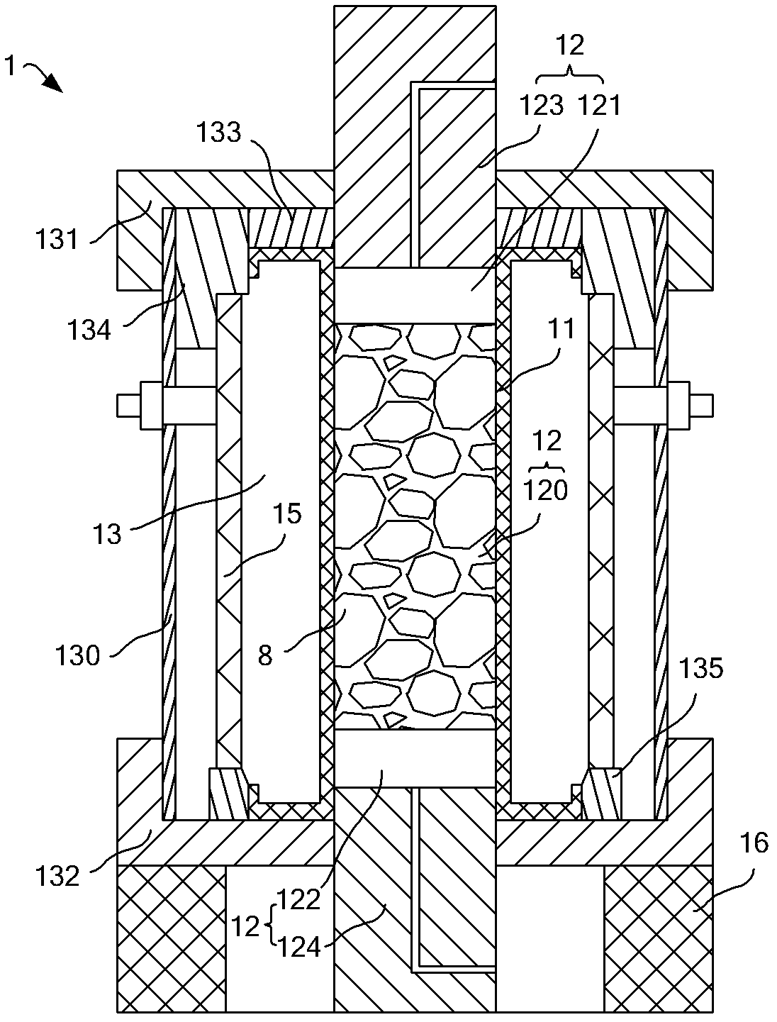
[0029] The rock-soil rheological test method is to simulate different stress field environments of the rock and soil by applying pressure to the rock-soil test pieces set in the pressure chamber, and then by detecting the change parameters of the rock-soil test pieces in the above-mentioned environment to simulate the actual rock-soil Evaluation of soil changes under different stress field environments. In the present invention, the axial pressure and radial pressure of the rock-soil test piece located in the pressure chamber are absolutely isolated, so that the...


PUM


Abstract

The invention discloses rock soil rheological test equipment, which comprises a pressure chamber, a test bench, an axial environment system, a radial environment system, an energy supply system, a detection system and a control and analysis system, wherein the pressure chamber comprises an axial pressure chamber and an annular pressure chamber; the axial pressure chamber comprises an upper pressure chamber, a test piece chamber and a lower pressure chamber, which are sequentially laminated; a rock soil test piece is arranged in the test piece chamber; oil liquid under adjustable pressure is injected into the annular pressure chamber, the upper pressure chamber and the lower pressure chamber; the annular pressure chamber surrounds the radial direction of the axial pressure chamber; and the axial pressure chamber is formed by an internal space of an elastic sheath. The rock soil rheological test equipment has the advantages that the annular pressure chamber and the axial pressure chamber in the pressure chamber are isolated from each other by using the elastic sheath, and the axial pressure and radial pressure of the rock soil test piece in the pressure chamber are absolutely isolated, so the axial pressure and radial pressure of the rock soil test piece in the test piece chamber are independent of each other.

Description

technical field [0001] The invention relates to a rock-soil rheological test equipment. Background technique [0002] The rheological properties of rock and soil mainly include creep characteristics and force relaxation characteristics. The study of rheological properties of rock and soil is very important for the quality control of geotechnical engineering, safe operation, soft rock support and rock and soil mechanics research, especially for deep rock and soil Engineering and geomechanics are more important. The research on the rheological characteristics of rock and soil mainly focuses on the study of the failure mechanism of rock and soil, so as to promote the improvement of quality control, safe operation and soft rock support level of geotechnical engineering. At present, the rheological test of rock and soil mainly uses a triaxial rheometer, which can exert pressure on the radial and axial directions of the rock and soil, but the radial pressure and the axial pressur...

Claims


Application Information

Patent Timeline
IPC IPC(8): G01N3/18G01N3/02
Inventor 何满潮孙晓明赵健
Owner CHINA UNIV OF MINING & TECH (BEIJING)
Why Eureka
Try Eureka