
Light-emitting diode (LED) circuit board component

A technology of LED circuit boards and flexible circuit boards, which is applied in the direction of printed circuits connected with non-printed electrical components, can solve the problems of large heat generation, high copper foil cost, high material cost, etc. The effect of prolonging the working length and reducing the production cost

Inactive Publication Date: 2012-08-01
惠州市串联电子科技有限公司
View PDF8 Cites 6 Cited by
  • Summary
  • Abstract
  • Description
  • Claims
  • Application Information

AI Technical Summary

Problems solved by technology

[0005] However, since resistance is inevitable when the LED circuit board is too long, it should not be too long in series, otherwise it will cause excessive voltage attenuation
[0006] Moreover, if the LED circuit board is too long, and there are too many series groups of LED lamps connected in parallel, the main lines on both sides of the circuit board need to load too much current, resulting in excessive heat generation. This heat, together with the heat of the LED lamp itself, is not easy to dissipate quickly. , causing the LED lamp to work at too high a temperature, which in turn affects the luminous performance and reliability of the LED lamp and its service life
[0007] For this reason, circuit boards of the prior art often adopt wider and thicker copper foil circuit layers, because the cost of copper foil is high, this will inevitably lead to higher material costs, and its final heat dissipation performance and work reliability not ideal
For example, in the actual application of this prior art LED circuit board, the total length after connection is generally not more than 5 meters, otherwise the voltage decays too much, it is difficult to ensure the normal operating voltage of all LED lamps, and the heat generation is too large and the heat dissipation The effect is not good, and it is difficult to apply in high-demand applications

Method used


Image

  • Light-emitting diode (LED) circuit board component
  • Light-emitting diode (LED) circuit board component

Examples


Embodiment Construction

[0028] Hereinafter, a flexible printed circuit board suitable for mounting LEDs and other components will be used as a specific embodiment to describe the present invention in more detail. It should be understood that the present invention is not only applicable to single-sided flexible printed circuit boards, but also applicable to double-sided flexible printed circuit boards or multilayer LED circuit boards, and is also applicable to rigid circuit boards (also referred to as "hard boards" in the industry).

[0029] The term "single-sided flexible printed wiring board" means that a circuit is provided on only one side of the flexible printed wiring board. The term "double-sided flexible printed wiring board" means that the flexible printed wiring board is provided with lines on both sides.

[0030] Before describing the present invention in detail, those skilled in the art should understand that “element” should be understood in the broadest sense in this application, that is, it ...


PUM


Abstract

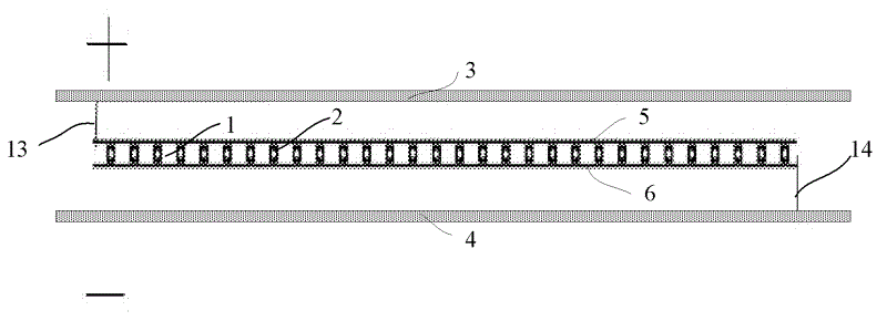
The invention relates to a light-emitting diode (LED) circuit board component. The LED circuit board component comprises one or more LED circuit boards (1), a positive main wire (3) and a negative main wire (4), a plurality of serially-connected LED groups are arranged on each LED circuit board (1), each serially-connected LED group comprises a plurality of serially-connected LEDs (2), and the serially-connected LED groups are connected in parallel to the positive circuit (5) and the negative circuit (6) of the LED circuit board (1); the positive main wire (3) and the negative main wire (4) are separated from the LED circuit boards (1) by a certain distance; and a positive circuit (5) is connected with the positive main wire (3) through a positive connecting wire (13), and the negative circuit (6) is connected with the negative main wire (4) through the negative connecting wire (14). The LED circuit board component is low in manufacturing cost and high in radiating performance, the reliability of a product is greatly improved, the actual service life is greatly prolonged, and working length of the product is increased.

Description

Technical field [0001] The invention relates to the field of LED circuit boards, in particular to a new type of LED circuit board assembly. Background technique [0002] In the prior art LED circuit board, the main line of this prior art LED circuit board product is on the circuit board, that is, the main line sum located on both sides of the circuit board integrated with the circuit board, the main line and itself are the circuit A part of the conductive circuit layer of the board is generally copper foil, which is mainly used to guide the working current of the LED. [0003] In practical applications, for this kind of prior art LED circuit board, generally about 3 LED lights are connected in series to form a group, so that a number of LED lamp series groups are formed on the LED circuit board, and then the main lines on both sides of the circuit board These LED lights are connected in parallel in series. [0004] Typically, the head and end of the circuit board product have posit...

Claims


Application Information

Patent Timeline
Patent Type & Authority Applications(China)
IPC IPC(8): H05K1/18
Inventor 田茂福
Owner 惠州市串联电子科技有限公司
Learn More