Thermal insulation structure and high-temperature furnace

A high-temperature furnace and insulation layer technology, applied in the direction of single crystal growth, polycrystalline material growth, crystal growth, etc., can solve the problems of unsatisfactory insulation effect, high thermal conductivity of alumina, and volatilization of carbon atoms.

Active Publication Date: 2012-08-08
JIANGSU XIEXIN SOFT CONTROL EQUIP TECH DEV
View PDF8 Cites 12 Cited by
  • Summary
  • Abstract
  • Description
  • Claims
  • Application Information

AI Technical Summary

Problems solved by technology

For example, the current sapphire crystal growth furnace realizes crystal growth in a high temperature environment higher than 2000 ° C. The insulation materials are mainly tungsten and molybdenum in the high temperature area and alumina hollow balls or zirconia bricks in the low temperature area. The distance from the heating chamber The nearer area is the high temperature area, and the area farther away from the heating chamber is the low temperature area. The heat preservation mechanism is mainly to reduce the heat loss through the reflection of heat on the tungsten and molybdenum materials in the high temperature area, and to reduce the heat loss in th

Method used


Image

  • Thermal insulation structure and high-temperature furnace
  • Thermal insulation structure and high-temperature furnace
  • Thermal insulation structure and high-temperature furnace

Examples


Embodiment 1

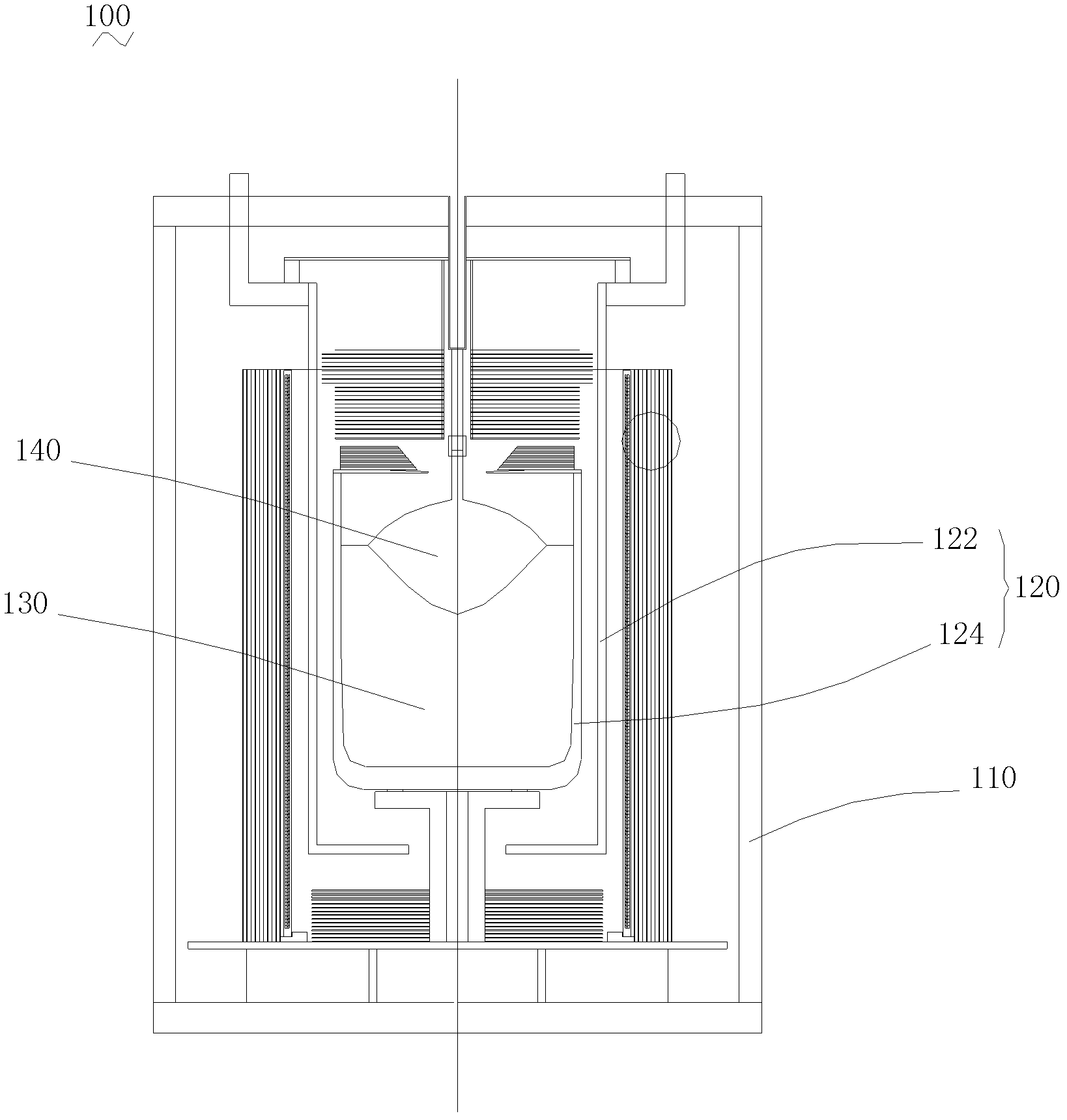
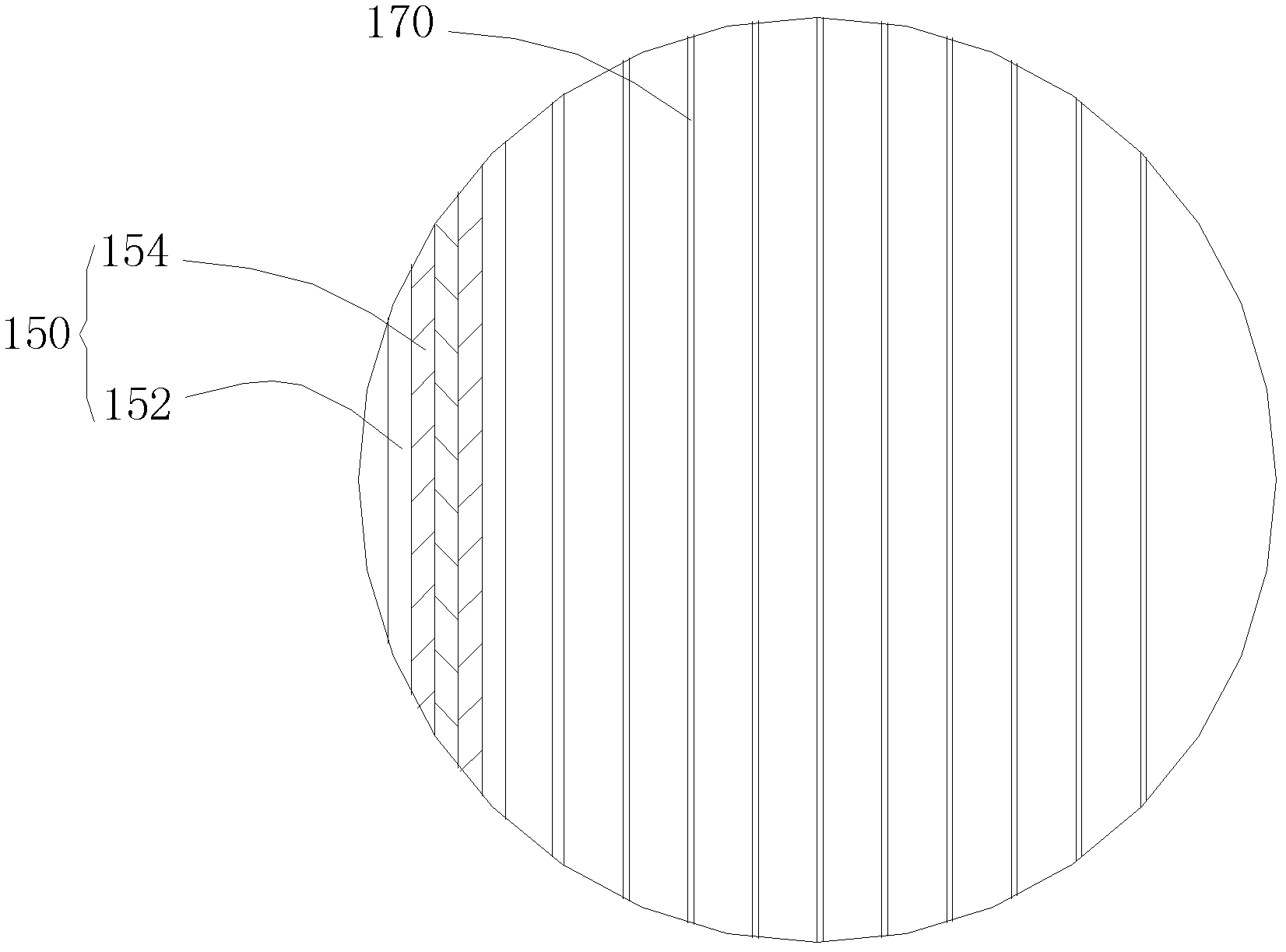
[0037] Inside the tungsten cylinder 152 with a thickness of 10mm, a certain manufacturing method is used to fill the interior with 3 layers of carbon felt material 154 with a thickness of 2mm, that is, the outer layer of the heat preservation structure is the tungsten cylinder 152, and the inner layer is 3 layers of carbon felt material with a thickness of 2mm. 154. Then install it inside the sapphire crystal growth furnace as its side insulation layer structure 150, and use the installed sapphire crystal growth furnace to grow sapphire crystal 140. Due to its good heat preservation effect reduces the power of the crystal in each stage, thus reducing the energy consumption of the sapphire furnace. At the same time, due to the reduction of the power of the sapphire furnace, the voltage is basically constant, thereby reducing the current value. According to the ampere force formula, the ampere force existing in the tungsten rod heater 122 is much reduced, so that the deformation...

Embodiment 2

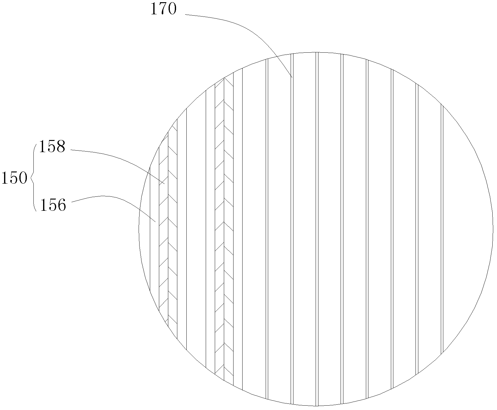
[0039] Inside the molybdenum cylinder 156 with a thickness of 10mm, a certain process is used to fill it with 2 layers of carbon felt material 158 with a thickness of 3mm, that is, the outer layer of the heat preservation structure is tungsten cylinder 156, and the inner layer is 2 layers of carbon felt material with a thickness of 3mm. 158. Then install it inside the sapphire crystal growth furnace as its side insulation layer structure 150, and grow the sapphire crystal 140 in the installed sapphire crystal growth furnace. Due to its good heat preservation effect reduces the power of the crystal in each stage, thus reducing the energy consumption of the sapphire furnace. At the same time, due to the reduction of the power of the sapphire furnace, the voltage is basically constant, thereby reducing the current value. Similarly, according to the ampere force formula, the ampere force existing in the tungsten rod heater 122 is greatly reduced, so that the deformation of the tun...


PUM


Abstract

The invention relates to a thermal insulation structure, which comprises an outer layer and an inner layer, and the inner layer is sealed inside the outer layer, and is made of thermal insulation material. The thermal insulation structure is of a sandwich structure formed by the inner layer and the outer layer, the inner layer is sealed inside the outer layer, and by combining the characteristic of the heat reflection of the outer layer with the characteristic of the heat insulation of the inner layer, the purpose of thermal insulation can be better realized, and the effect of thermal insulation can be remarkably improved in comparison with material only using the outer layer to reflect heat. In addition, the invention also provides a high-temperature furnace using the thermal insulation structure.

Description

technical field [0001] The invention relates to the technical field of high-temperature furnace equipment, in particular to a heat preservation structure and a high-temperature furnace. Background technique [0002] At present, due to limited high-temperature resistant materials, and due to technical and cost constraints, many high-temperature equipment consumes a lot of power and costs, and the thermal field is still unstable. And these all depend on a very important factor, that is, the thermal insulation effect of the thermal insulation material. High-temperature materials must not only meet the application of high-temperature environments, but also meet the requirements of not polluting the prepared materials at high temperatures. For example, the current sapphire crystal growth furnace realizes crystal growth in a high temperature environment higher than 2000 ° C. The insulation materials are mainly tungsten and molybdenum in the high temperature area and alumina hollo...

Claims


Application Information

Patent Timeline
IPC IPC(8): C30B29/20C30B35/00
Inventor 田义良薛抗美徐养毅赵玉兵
Owner JIANGSU XIEXIN SOFT CONTROL EQUIP TECH DEV
Why Eureka
Try Eureka