Pressure taking device for steam pocket pressure measurement

A steam drum pressure and steam drum technology, which is applied in the direction of fluid pressure measurement using liquid as a pressure-sensitive medium, can solve problems such as damage to the transmitter, deformation of the pressure transmitter diaphragm, and crystal blockage of the pressure-taking pipeline. The effect of prolonging life, reducing inaccurate pressure measurement, and ensuring reliability

Inactive Publication Date: 2012-08-08
SHANXI LANHUA SCI TECH VENTURE
View PDF5 Cites 2 Cited by
  • Summary
  • Abstract
  • Description
  • Claims
  • Application Information

AI Technical Summary

Problems solved by technology

However, with the need for energy saving and emission reduction, most co-production urea plants send the desalination waste liquid from the urea plant to the vaporization jacket steam drum and the blast gas recovery boiler drum after treatment, and use the desalination waste liquid to replace the desalted water. The analyzed waste liquid after treatment still contains a part of NH3 and CO2, oil stains and other impurities that are easy to crystallize and clog. The traditional pressure measurement method of boiler drum pressure is direct pressure measurement, such as figure 1 , after the steam drum medium is changed to analytical waste liquid, there is crystallization blockage in the pressure-taking pipeline and the pressure measuring device, so that the actual pressure in the steam drum cannot be truly measured
Especially for pressure measurement, once the bellows of the pressure transmitter is blocked, the bellows will be deformed and damaged
Therefore, the traditional pressure taking method will cause the pressure measurement of the steam drum to fail to reflect the real pressure on the one hand, and on the other hand, it will deform the bellows of the pressure transmitter and damage the transmitter

Method used


Image

  • Pressure taking device for steam pocket pressure measurement
  • Pressure taking device for steam pocket pressure measurement
  • Pressure taking device for steam pocket pressure measurement

Examples


Embodiment Construction

[0019] The present invention will be further described below with reference to the accompanying drawings and embodiments.

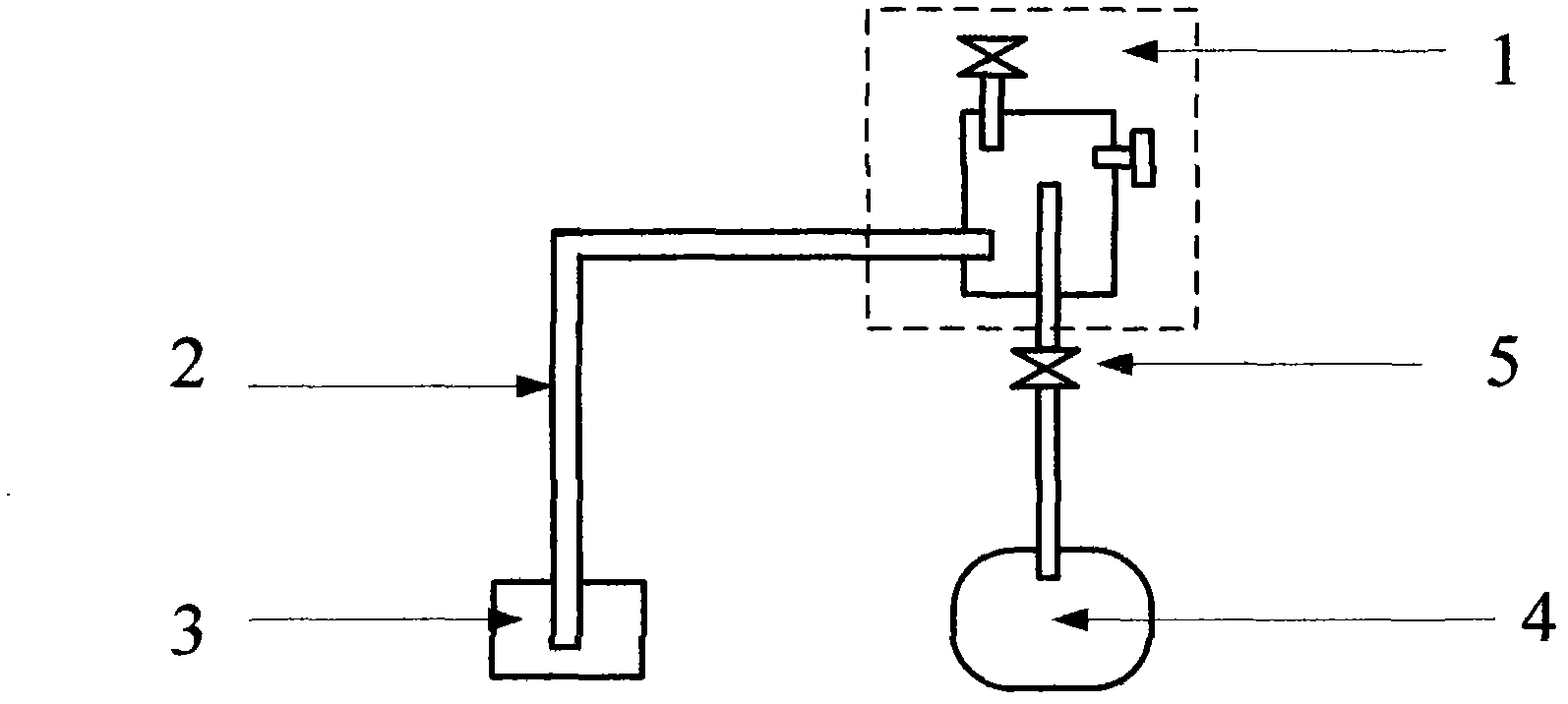
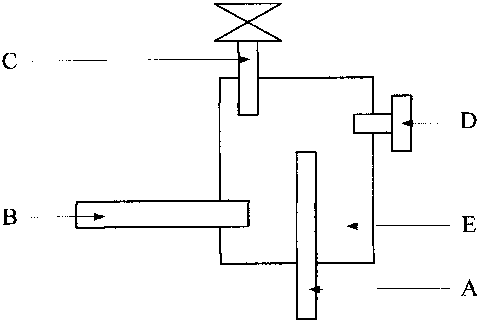
[0020] Reference to embodiments of the present invention figure 2 , 3 shown.

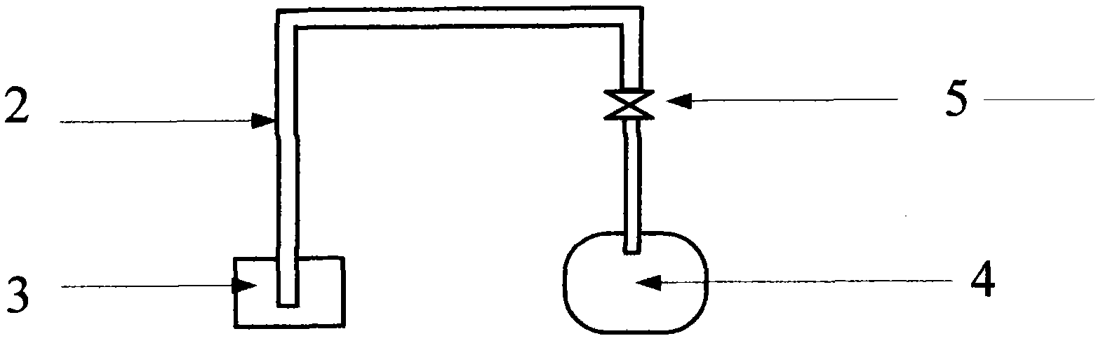
[0021] A steam drum pressure measuring and taking device, the steam drum pressure measuring and taking device 1 comprises a main body part E, a conduit part and an exhaust plug D, and is connected with a pressure transmitter diaphragm 3 through a pressure guiding pipe 2, The steam drum pressure measuring and taking device 1 is connected with the steam drum 4 through the steam drum pressure root valve 5, and it is characterized in that: the conduit part is the first conduit A, the second conduit B and the third conduit C, which are respectively connected On the bottom, side and top of the main body part E, and extending into the main body part E, the first conduit A is connected to the steam drum 4 through the steam drum tap root valve 5, and the second conduit B is connected...


PUM

PropertyMeasurementUnit
diameteraaaaaaaaaa
heightaaaaaaaaaa
thicknessaaaaaaaaaa

Abstract

The invention discloses a pressure taking device for steam pocket pressure measurement. The device (1) comprises a main body part (E), a conduit part and an exhausting screwed plug (D), wherein the device is connected with a pressure transmitter film box (3) through a pressure guide pipe (2); the conduit part is divided into a first conduit (A), a second conduit (B) and a third conduit (C) which are connected with the bottom part, the side part and the top part of the main body part (E) respectively and extend into the main body part (E); the first conduit (A) is connected with a steam pocket (4) through a steam pocket pressure-taking root valve (5); the second conduit (B) is connected with the pressure guide pipe (2); an instrument needle valve is arranged on the third conduit (C); and the exhausting screwed plug (D) is in threaded connection with the main body part (E). The device has a simple structure, is convenient to mount and use, and greatly prolongs the service life of a pressure transmitter.

Description

technical field [0001] The invention relates to a pressure-taking device, in particular to a steam-drum pressure-measuring device suitable for boiler steam drum medium which adopts urea desorption waste liquid or other medium easy to crystallize and block to replace desalinated water. Background technique [0002] In the production process of chemical fertilizer and chemical enterprises, the boiler jacket boiler and blowing gas recovery boiler are the main energy-saving devices for heat energy recovery and utilization. The blowing gas and the purge gas released by the synthesis device are burned to produce steam, and the steam is effectively used in the vaporization device. The original design of the steam drum liquid addition adopts industrial desalination water, and the water quality is better. However, with the need for energy saving and emission reduction, most co-production urea plants treat the analyzed waste liquid of the urea unit, and then send it to the vaporizatio...

Claims


Application Information

Patent Timeline
Patent Type & Authority Applications(China)
IPC IPC(8): G01L7/18
Inventor 魏朝阳
Owner SHANXI LANHUA SCI TECH VENTURE
Why Eureka
Try Eureka