
Uninterrupted motive power system for oil pumping machine in oil field

A power system and pumping unit technology, applied in the direction of mining fluid, electrical components, wellbore/well components, etc., can solve the problems of manual guarding, low pumping efficiency, high cost, etc., and achieve the elimination of environmental pollution and simple facility configuration , good economical effect

Inactive Publication Date: 2012-08-08
重庆金之川动力机械有限公司
View PDF4 Cites 1 Cited by
  • Summary
  • Abstract
  • Description
  • Claims
  • Application Information

AI Technical Summary

Problems solved by technology

However, if the associated gas of each oil well is collected through pipelines, since the total amount of associated gas is small and the location of the oil wells is scattered, this centralized comprehensive utilization method needs to be equipped with a large number of pipelines and ancillary facilities, and the cost is relatively high and economical. Even if some gas generators can be used for power generation with associated gas, their work is extremely unstable, and continuous power supply to pumping units cannot be guaranteed. The conversion rate of associated gas is less than 40%, and the pumping efficiency is low and manual protection is required.

Method used


Image

  • Uninterrupted motive power system for oil pumping machine in oil field
  • Uninterrupted motive power system for oil pumping machine in oil field
  • Uninterrupted motive power system for oil pumping machine in oil field

Examples


Embodiment Construction

[0020] The following will clearly and completely describe the technical solutions in the embodiments of the present invention with reference to the accompanying drawings in the embodiments of the present invention. Obviously, the described embodiments are only some, not all, embodiments of the present invention. Based on the embodiments of the present invention, all other embodiments obtained by persons of ordinary skill in the art without creative efforts fall within the protection scope of the present invention.

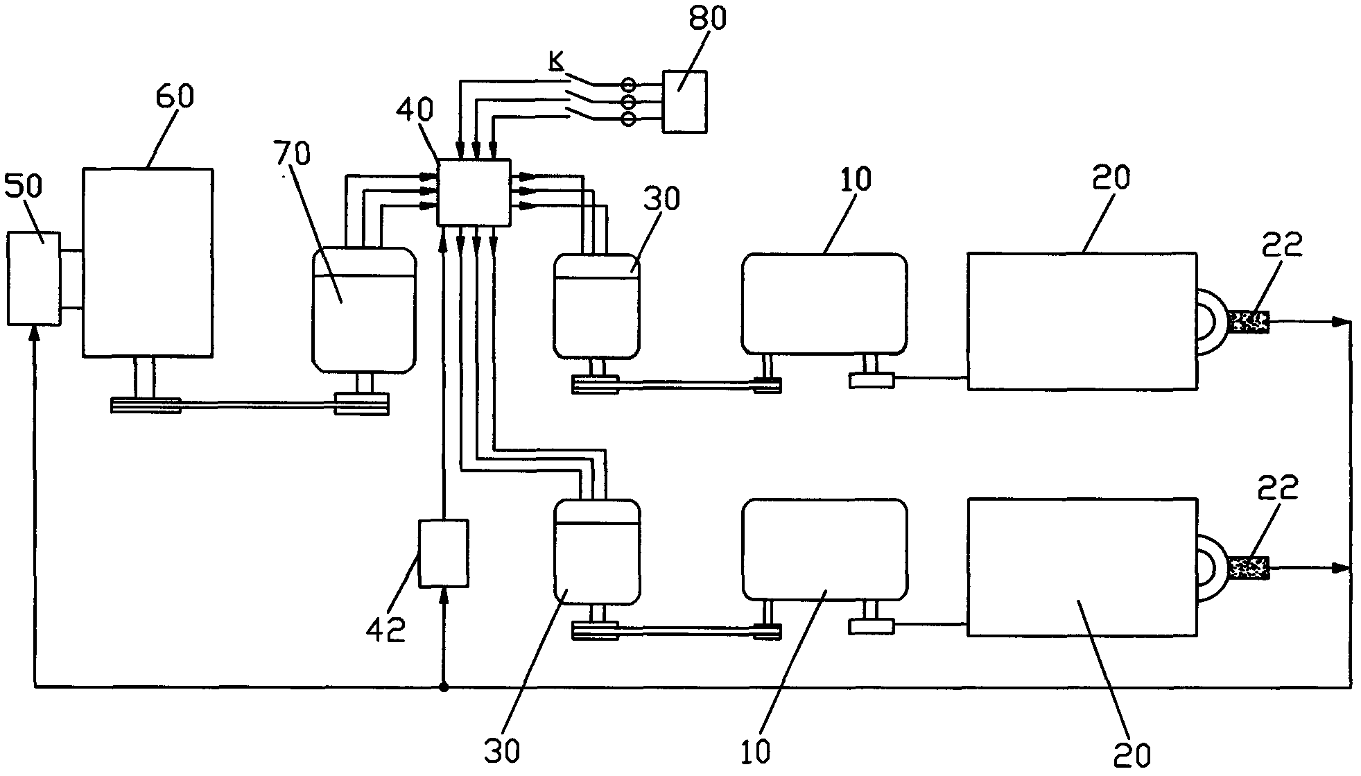
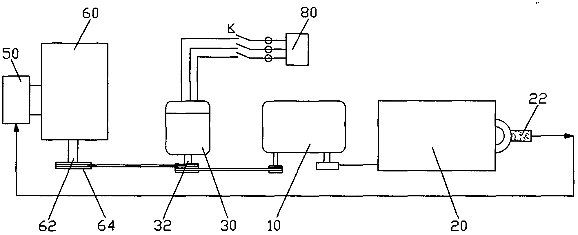
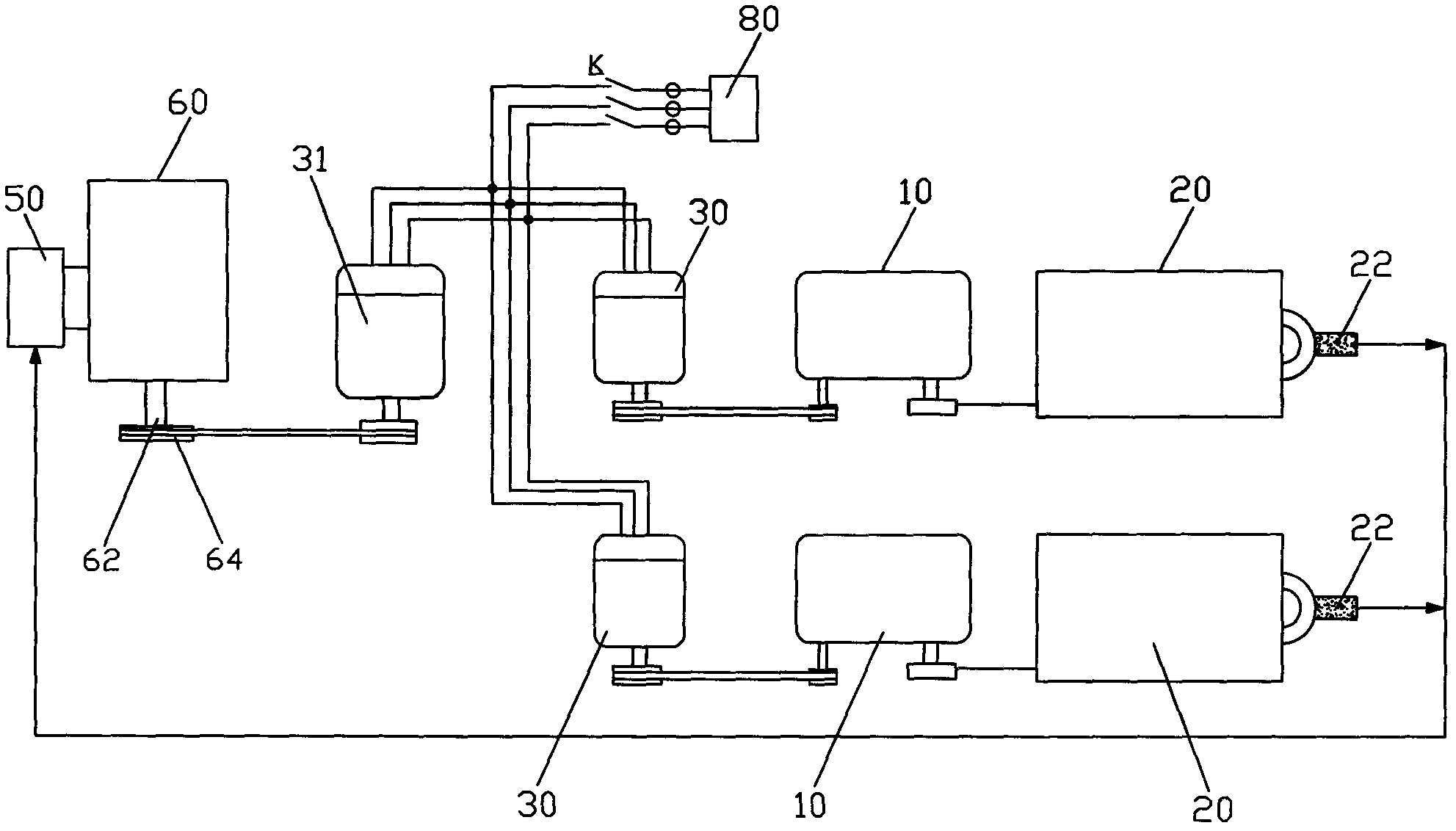
[0021] Such as figure 1 As shown, the present invention provides an uninterrupted power system of an oilfield pumping unit, which includes a pumping unit 20 connected with a speed reducer 10 and a motor 30, the input end of the speed reducer 10 is connected with the output shaft of the motor 30, It also includes an automatic switching controller 40, a pressure sensor 42 for real-time detection of the associated gas passing through the associated gas outlet port 22 ...


PUM


Abstract

The invention discloses an uninterrupted motive power system for an oil pumping machine in an oil field. The uninterrupted motive power system comprises an oil pumping machine and an electric motor, wherein the oil pumping machine is connected with a speed reducing machine, the input end of the speed reducing machine is connected with an output shaft of the electric motor, the uninterrupted motive power system also comprises an automatic switching controller, an air pressure sensor, a gas mixing device, an engine and a power generator, wherein the gas mixing device is connected with an associated gas outlet end, the power generator is connected between the engine and the motor, when the associated gas is sufficient, the engine uses the associated gas for providing the motive power for the oil pumping machine, when the associated gas is interrupted or insufficient, the commercial power is automatically switched to supply electricity to the motor, and the oil pumping machine can realize the uninterrupted movement; and when the commercial power is unavailable, the automatic switching controller is automatically switched into a mode of using the associated gas and / or fuel oil for driving the power generator to generate electricity so that an output shaft of the motor maintains the uninterrupted rotation, and the oil pumping machine is ensured to continuously work. The uninterrupted motive power system has the advantages that the associated gas, the electric energy and the fuel oil are used as complementary energy sources for providing the motive power for the oil pumping machine, the hidden danger of environment pollution can be eliminated, the continuous work of the oil pumping machine is realized, in addition, the utilization rate is higher, and the economic performance is better.

Description

technical field [0001] The invention relates to the technical field of oil field pumping units, in particular to a power system for oil field pumping units. Background technique [0002] The pumping unit is the most important oil production equipment in the oil field. Its working principle is to use a crank mechanism to drive the sucker rod to reciprocate up and down in the oil well after the motor is decelerated. The power of the pumping unit in the oil field is usually provided by the motor or the engine respectively. Under the condition of power supply, the motor is mostly used to drive the pumping unit through the reducer. The engine drives the pumping unit to work. [0003] During the working process of the pumping unit, associated gas will be generated, and the volume of this associated gas is unstable, showing a phenomenon of sometimes more and sometimes less. In order to prevent the associated gas from polluting the surrounding environment, most of the associated g...

Claims


Application Information

Patent Timeline
Patent Type & Authority Applications(China)
IPC IPC(8): H02J9/06E21B43/00
Inventor 王秋勇
Owner 重庆金之川动力机械有限公司
Learn More