Rocker type upper limb rehabilitation device and method for performing rehabilitation training by aid of rocker type upper limb rehabilitation device
A rehabilitation device and rocker-type technology, applied in the direction of passive exercise equipment, sports accessories, gymnastics equipment, etc., can solve the problems of inability to realize three-dimensional space movement, lack of flexibility, and patient discomfort, and achieve diversified training modes , Simple and compact structure, wide crowd effect
- Summary
- Abstract
- Description
- Claims
- Application Information
AI Technical Summary
Problems solved by technology
Method used
Image

Examples
Embodiment Construction
[0047] The present invention will be further described in detail below in conjunction with the accompanying drawings and embodiments. It should be noted that the following embodiments are intended to facilitate the understanding of the present invention, but do not limit it in any way.
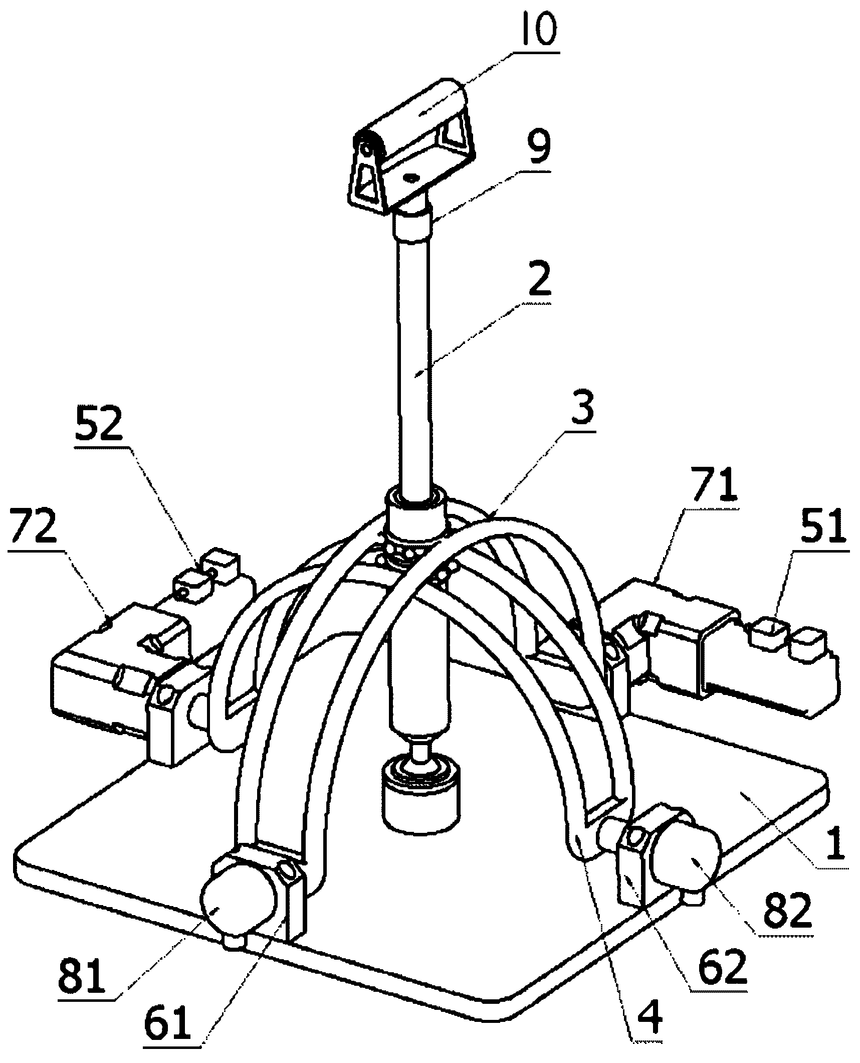
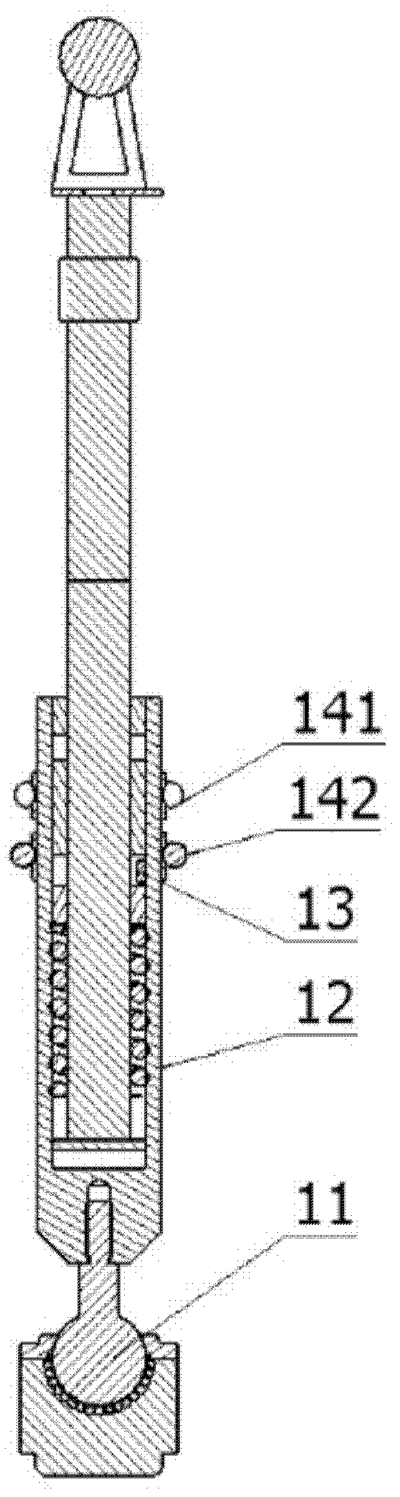
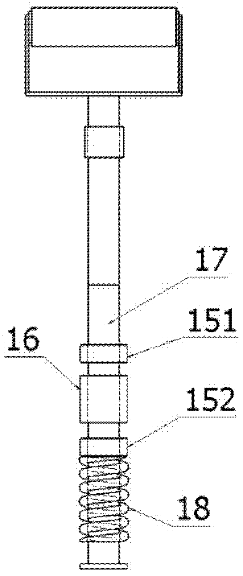
[0048] Figure 1 to Figure 4The labels in are: base 1, telescopic rocker 2, outer arc track 3, inner arc track 4, first servo motor 51, second servo motor 52, bearing housings (61, 62), first reducer 71 , second reducer 72, first photoelectric encoder 81, second photoelectric encoder 82, six-axis force sensor 9, handle 10, universal ball 11, rocker shell 12, position sensor 13, sliding bearing (141,142 ), positioning bearing (151, 152), mover 16, stator 17, spring 18, computer 19, first servo motor driver 21, second servo motor driver 22, linear motor driver 23, signal conditioner 24, motion control card 25. Display 26.
[0049] Such as figure 1 As shown, the rocker type upper limb rehabili...
PUM
 Abstract
Description
Claims
Application Information
PatSnap Eureka turns technology decisions into work you can execute. Powered by our Innovation Knowledge Graph, it runs expert workflows across engineering, life sciences, materials and intellectual property. Get your review-ready output in minutes.


