Dehydration process and equipment for biomass solid

A technology of dehydration equipment and biomass, which is applied in the direction of drying solid materials, lighting and heating equipment, and method combination to dry solid materials, etc., can solve the problem of high cost, and achieve the effect of reducing moisture content and improving fuel value.

Inactive Publication Date: 2012-08-15
太原正阳环境工程有限公司
View PDF5 Cites 2 Cited by
  • Summary
  • Abstract
  • Description
  • Claims
  • Application Information

AI Technical Summary

Problems solved by technology

The high water content makes the sludge have a negative calorific value, and it needs to consume a lot of fuel to remove the moisture in the sludge, so the cost of drying and incineration is very high

Method used


Image

  • Dehydration process and equipment for biomass solid
  • Dehydration process and equipment for biomass solid
  • Dehydration process and equipment for biomass solid

Examples


Embodiment 1

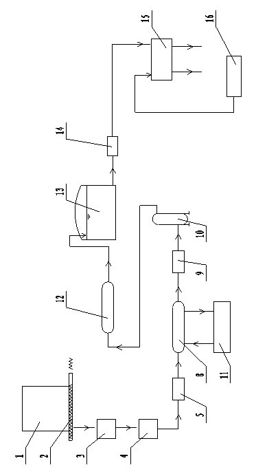
[0038] Such as figure 1 As shown, the present invention is a kind of dehydration equipment that is used for biomass solid, comprises crushing device 3, filter device 4, heating device 8, pressure vessel 10, cooling device 12, liquid storage tank 13 and dehydrator 15, the structure of crushing device 3 The inlet is connected to the outlet of the bin 1 containing biomass solids through a conveyor 2, the outlet of the crushing device 3 is connected to the inlet of the filter device 4, and the outlet of the filter device 4 is connected to the inlet of the heating device 8 through the first pressure pump 5, The outlet of the heating device 8 is connected to the inlet of the pressure vessel 10, the outlet of the pressure vessel 10 is connected to the inlet of the cooling device 12, the outlet of the cooling device 12 is connected to the inlet of the liquid storage pool 13, and the outlet of the liquid storage pool 13 is passed through the lysate The delivery pump 14 is connected wit...

Embodiment 2

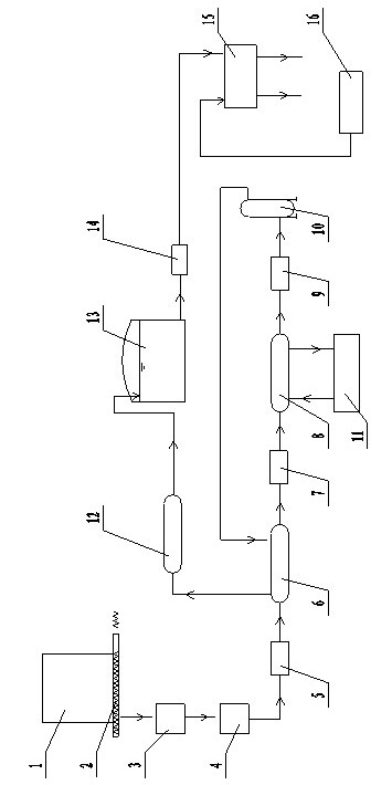
[0043] Such as figure 2 As shown, the present invention is a kind of dehydration equipment that is used for biomass solid, comprises crushing device 3, filter device 4, heating device 8, pressure vessel 10, cooling device 12, liquid storage tank 13 and dehydrator 15, the structure of crushing device 3 The inlet is connected to the outlet of the bin 1 containing biomass solids through a conveyor 2, the outlet of the crushing device 3 is connected to the inlet of the filter device 4, and the outlet of the filter device 4 is connected to the inlet of the heating device 8 through the first pressure pump 5, The outlet of the heating device 8 is connected to the inlet of the pressure vessel 10, the outlet of the pressure vessel 10 is connected to the inlet of the cooling device 12, the outlet of the cooling device 12 is connected to the inlet of the liquid storage pool 13, and the outlet of the liquid storage pool 13 is passed through the lysate The delivery pump 14 is connected wi...

Embodiment 3

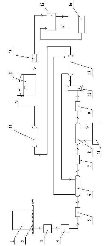
[0049] Such as image 3 As shown, the present invention is a kind of dehydration equipment that is used for biomass solid, comprises crushing device 3, filter device 4, heating device 8, pressure vessel 10, cooling device 12, liquid storage tank 13 and dehydrator 15, the structure of crushing device 3 The inlet is connected to the outlet of the bin 1 containing biomass solids through a conveyor 2, the outlet of the crushing device 3 is connected to the inlet of the filter device 4, and the outlet of the filter device 4 is connected to the inlet of the heating device 8 through the first pressure pump 5, The outlet of the heating device 8 is connected to the inlet of the pressure vessel 10, the outlet of the pressure vessel 10 is connected to the inlet of the cooling device 12, the outlet of the cooling device 12 is connected to the inlet of the liquid storage pool 13, and the outlet of the liquid storage pool 13 is passed through the lysate The delivery pump 14 is connected wit...


PUM

PropertyMeasurementUnit
diameteraaaaaaaaaa

Abstract

The invention relates to a dehydration process and equipment for a biomass solid, and belongs to the technical field of biomass dehydration. The invention aims at provided with a dehydration process and the equipment which have the advantages that slight energy source is consumed, the cells in the biomass solid are ruptured, the moisture is dissolved out, the water ratio of the biomass solid is greatly reduced, and the burning value of the biomass solid is improved. The technical scheme adopted by the dehydration process for the biomass solid is as follows: the dehydration process is performed according to the following steps of: 1, fracturing the biomass solid; 2, filtering the biomass solid after fracture; 3, putting the biomass solid into a heating unit, heating, and then entering a pressure container to stay for 10 minutes, thus obtaining a biomass solid cracking liquid; 4, putting the biomass solid cracking liquid into a cooling unit and cooling; and 5, entering a water extractor and carrying out dehydration. The dehydration process and equipment provided by the invention are especially suitable for carrying out dehydration treatment on the biomass solid with higher water ratio.

Description

technical field [0001] The invention relates to a dehydration process and equipment for biomass solids, belonging to the technical field of biomass dehydration. Background technique [0002] Biomass refers to various organisms formed through photosynthesis, including all animals, plants and microorganisms. The so-called biomass energy is the energy form of solar energy stored in biomass in the form of chemical energy. It is directly or indirectly derived from the photosynthesis of green plants and can be converted into conventional solid, liquid and gaseous fuels. Inexhaustible and inexhaustible, it is a renewable energy source and the only renewable carbon source. At present, many countries are actively researching and developing biomass energy. Biomass can be stored in organic matter that can grow, such as plants, animals and microorganisms, usually including wood, forest waste, agricultural waste, aquatic plants, oil plants, urban and industrial organic waste, animal ma...

Claims


Application Information

Patent Timeline
Patent Type & Authority Applications(China)
IPC IPC(8): F26B7/00C02F11/12
CPCY02W10/37
Inventor 杨金凯胡忠民韩磊赵治平史英君
Owner 太原正阳环境工程有限公司
Why Eureka
Try Eureka