High-power wireless charging device

A wireless charging and charging device technology, applied in circuit devices, battery circuit devices, current collectors, etc., can solve problems such as difficult speed and real-time requirements, unstable operation of wireless charging systems, and poor stability of wireless feedback

Inactive Publication Date: 2012-08-15
CHERY AUTOMOBILE CO LTD
View PDF4 Cites 7 Cited by
  • Summary
  • Abstract
  • Description
  • Claims
  • Application Information

AI Technical Summary

Problems solved by technology

[0003] In the prior art, electromagnetic induction is basically used in high-power wireless power transmission, which is difficult to achieve full wireless feedback control and wireless power transmission power improvement
Since the feedback signal of the l

Method used


Image

  • High-power wireless charging device
  • High-power wireless charging device
  • High-power wireless charging device

Examples


Embodiment Construction

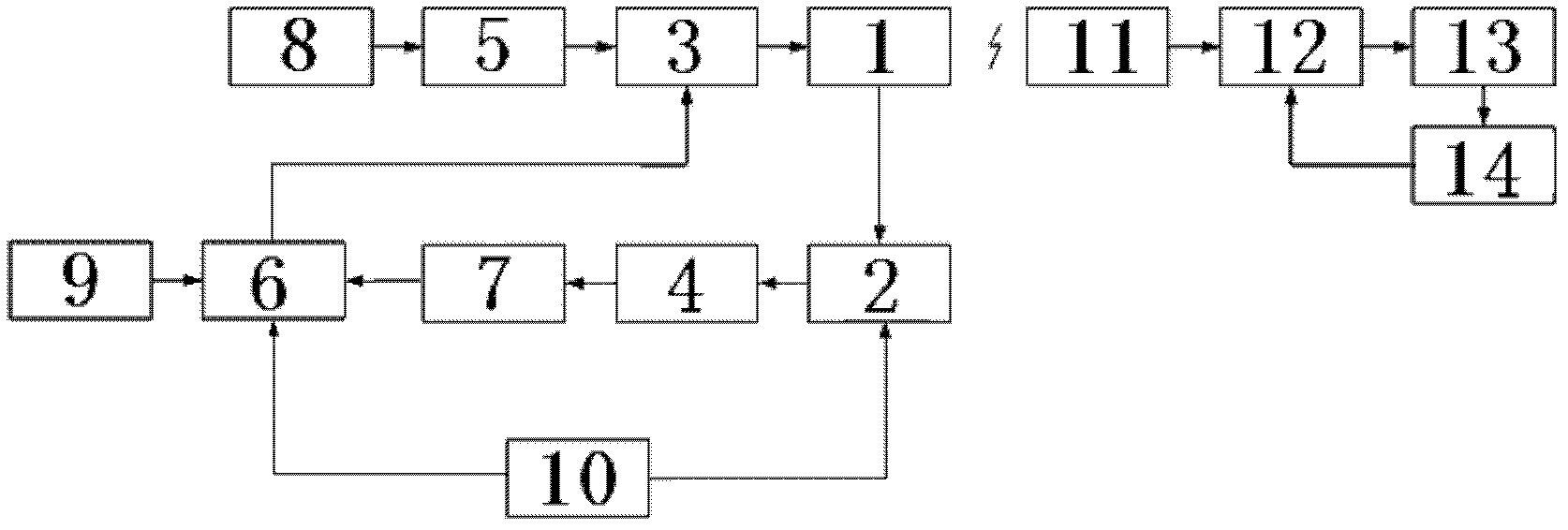
[0020] like figure 1 As shown, in the present invention, the power supply 8 is sequentially connected to the LC electromagnetic resonance circuit 1 through the bridge rectifier circuit 5 and the high-frequency switch 3, and the AD acquisition circuit 2 collects the current and voltage of the LC electromagnetic resonance circuit 1 through the RC filter circuit 4 and signal amplification. The circuit 7 is transmitted to the central processing unit 6 to form the transmitting end of the charging device; the electromagnetic resonance unit 11 is connected to the battery load 13 through the power management system 12, and the acquisition unit 14 then feeds back the current and voltage signals of the battery load 13 to the power management system 12 to form a charging device. The receiving end of the device, so as to independently detect and control the wireless transmission and reception, ensuring the stability of the entire charging device.

[0021] The central processing unit 6 is ...


PUM


Abstract

The invention discloses a high-power wireless charging device. The high-power wireless charging device is characterized in that a power supply accesses an LC electromagnetic resonance circuit sequentially by a bridge type rectification circuit and a high-frequency switch, an AD collection circuit collects current and voltage of the LC electromagnetic resonance circuit and then sends the current and voltage to a central processor by an RC filter circuit and a signal amplification circuit to form the transmitting end of the charging device; and a battery load accesses an electromagnetic resonance unit through a power supply management system, and the current and voltage signals of the battery load is fed back to the power supply management system by a collection unit to form the receiving end of the charging device. Due to the adoption of the circuit structure, the charging device has the advantages that 1, solving the problem that the wireless feed-back real-time property of the prior art is poor is solved by a high-voltage resonance manner; 2, the transmission distance of wireless power energy is lengthened; 3, the directivity of a magnetic field is strong, which is beneficial to distant transmission of wireless power energy; and 4, the harm on a human body is little.

Description

technical field [0001] The invention relates to the field of wireless charging, in particular to a high-power wireless charging device. Background technique [0002] Wireless charging is to charge electronic products through magnetic field loosely coupled resonance technology. The entire wireless charging system consists of two parts, one is the transmitting system connected to the power supply, and the other is the receiving system on the electronic product. As long as it is within a certain range, The power can be transmitted instantaneously from the transmitting system to the corresponding receiving system. [0003] In the prior art, electromagnetic induction is basically used in high-power wireless power transmission, and it is difficult to realize full wireless feedback control and increase of wireless power transmission power. Since the feedback signal of the load needs to be sent to the control unit in time, it is difficult to meet the real-time requirements of the w...

Claims


Application Information

Patent Timeline
IPC IPC(8): H02J7/02H02J17/00H02J50/12
Inventor 陈龙王新果
Owner CHERY AUTOMOBILE CO LTD
Why Eureka
Try Eureka