AI technical title is built by Patsnap AI team. It summarizes the technical point description of the patent document.
A reflection detection device, portable technology, applied in the direction of eye testing equipment, medical science, diagnosis, etc., to achieve high accuracy, easy to adjust the position of the instrument, and increase the portability of the instrument
Inactive Publication Date: 2012-08-22
NORTHEAST AGRICULTURAL UNIVERSITY +1
View PDF8 Cites 2 Cited by
Summary
Abstract
Description
Claims
Application Information
AI Technical Summary
This helps you quickly interpret patents by identifying the three key elements:
Problems solved by technology
Method used
Benefits of technology
Problems solved by technology
[0005] The purpose of the present invention is to provide a portable sow pupil reflex detection device for the current problem that there is no detection device for detecting the sow's health status specifically for the sow's pupil response
Method used
Image
Click on the blue label to locate the original text in one second.
Reading with bidirectional positioning of images and text.
Examples
specific Embodiment approach 1
[0022] Specific implementation mode one: the following combination figure 1 and figure 2 To describe this embodiment,
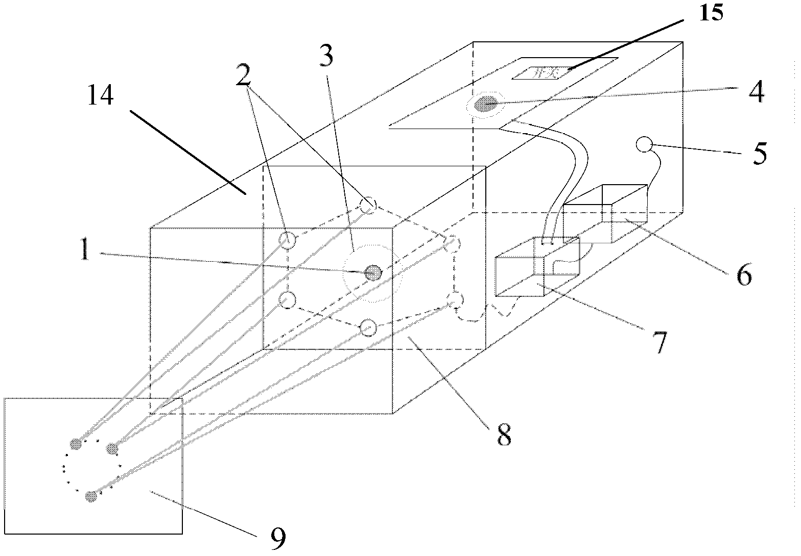
[0023] A portable sow pupil reflection detection device, which includes: an irradiation light source 1, six infrared laser heads 2, an adjustment knob 4, a power supply 6, a drive control circuit 7, a laser head fixing plate 8, a box body 14 and a power switch 15 ;
[0024] The bottom in the box body 14 is equipped with a power supply 6 and a drive control circuit 7, and the top outside of the box body 14 is provided with an adjustment knob 4 and a power switch 15,
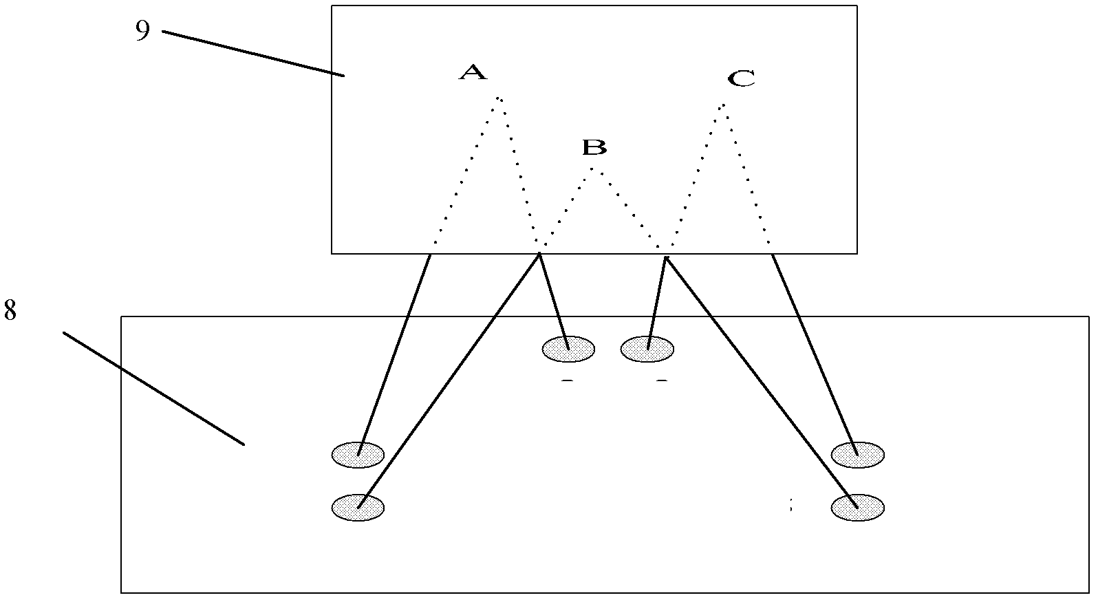
[0025] The irradiation light source 1 and the six infrared laser heads 2 are all fixed on the laser head fixing plate 8, and the irradiation light source 1 is located at the center of the regular hexagon formed by the six infrared laser heads 2;
[0026] The light source 1 converges the light at the central position of the working plane 9, and converges into a light spot at the central positi...
specific Embodiment approach 2
[0030] Specific implementation mode two: the following combination figure 2 Describe this embodiment, this embodiment is a further description of Embodiment 1,
[0031] A portable sow pupil reflection detection device, the drive circuit 7 is used to adjust the brightness of the light source emitted by the illumination light source 1 .
specific Embodiment approach 3
[0032] Specific implementation mode three: the following combination figure 2 Describe this embodiment, this embodiment is a further description of Embodiment 1,
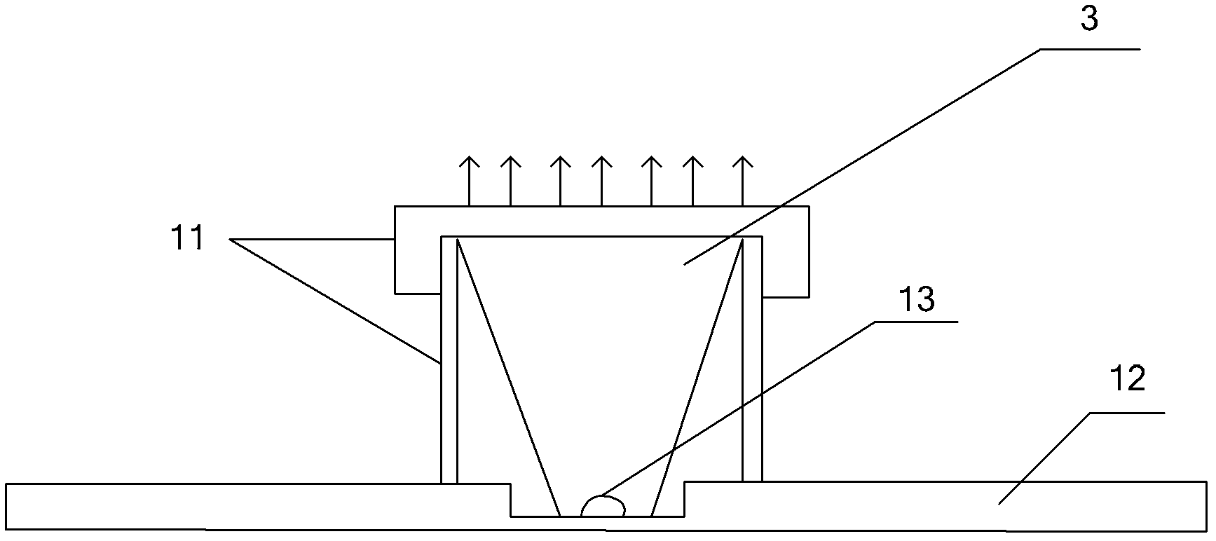
[0033] A portable sow pupil reflection detection device also includes six laser head fixtures, and each infrared laser head 2 is fixedly connected to the laser head fixing plate 8 through a laser head fixture. The laser head fixture in this embodiment is a direction-adjustable deck with two degrees of freedom, and has self-locking ability, which is used to adjust the angle of the fixed infrared laser head 2, and then realize the positioning on the working plane 9 During the process, the angle of the infrared laser head 2 is adjusted to correct the error of the infrared laser head 2 itself.
PUM
Abstract
A portable sow pupillary reflex detecting device relates to a detecting device and aims at solving the problem that no detecting instrument for detecting sow health condition reflected by sow pupils exists at present. A power supply and a drive control circuit are installed at the bottom in a box body, an adjusting knob and a power supply switch button are arranged on the outer side of the top, a radiationlight source and six infraredlaser heads are all fixed on a laser head fixing plate, and the radiationlight source is located at the central position of a regular hexagon formed by the six infraredlaser heads. The six infrared laser heads are divided into three groups, light rays emitted by every two adjacent infrared laser heads are intersected and converged into a point in the space, the control signal output end controlling the knob is connected with the control signal input end of the drive control circuit, the radiationlight sourcecontrol signal output end of the control circuit is connected with the control signal input end of the radiation light source, and the control signal output ends for the six infrared laser heads of the control circuit are respectively connected with the control signal input ends of the six infrared laser heads. The portable sow pupillary reflex detecting device is used for detecting sow pupils.
Description
technical field [0001] The invention relates to a detection device. Background technique [0002] The function of pupil contraction under light stimulation is called pupilreflex or response to light. The pupil will shrink immediately under strong light stimulation, and maintain it for a while, and then slowly dilate. The speed and degree of pupillary reactions on both sides are exactly the same, that is, the same amplitude changes at the same time. The pupillary response is slow or disappears is pathological. [0003] In the process of human medical clinical and experimental research, the inspection process of pupillary reflex includes direct response to light, indirect response to light and convergence reflex. In the detection of pupillary reflex, the test results may be affected by stress, or the measurement results may have large errors due to failure to cooperate with the inspection; the application of human pupil detection instruments to animals often has many proble...
Claims
Application Information
Patent Timeline
Application Date:The date an application was filed.
Publication Date:The date a patent or application was officially published.
First Publication Date:The earliest publication date of a patent with the same application number.
Issue Date:Publication date of the patent grant document.
PCT Entry Date:The Entry date of PCT National Phase.
Estimated Expiry Date:The statutory expiry date of a patent right according to the Patent Law, and it is the longest term of protection that the patent right can achieve without the termination of the patent right due to other reasons(Term extension factor has been taken into account ).
Invalid Date:Actual expiry date is based on effective date or publication date of legal transaction data of invalid patent.

