Method and device for manufacturing low-loss micro-nanometer fiber bragg grating sensor in chemical corrosion method

A grating sensor, chemical corrosion technology, which is applied in the direction of using optical devices to transmit sensing components, phase influence characteristic measurement, etc. Micro-nano fiber grating and other problems, to achieve the effect of being suitable for mass production, eliminating the sudden change of the corrosion interface, and having a simple and practical structure

Inactive Publication Date: 2012-08-22
ZHEJIANG UNIV
View PDF8 Cites 6 Cited by
  • Summary
  • Abstract
  • Description
  • Claims
  • Application Information

AI Technical Summary

Problems solved by technology

However, this technology illustrates the application capabilities of micro-nano fiber gratings in the field of sensing, but does not consider the large optical loss caused by the corrosion process.
It is known from experiments that this method cannot obtain very fine micro-nano fiber gratings, thus limiting the detection sensitivity of micro-nano fiber grating sensors; at the same time, the poor signal-to-noise ratio caused by large transmission loss will also seriously affect the micro-nano fiber gratings. Practical Detection Applications of Sensors

Method used


Image

  • Method and device for manufacturing low-loss micro-nanometer fiber bragg grating sensor in chemical corrosion method
  • Method and device for manufacturing low-loss micro-nanometer fiber bragg grating sensor in chemical corrosion method
  • Method and device for manufacturing low-loss micro-nanometer fiber bragg grating sensor in chemical corrosion method

Examples


Embodiment

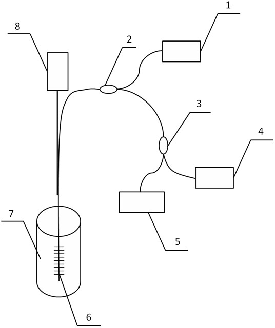
[0029] like figure 1 As shown, the device includes a broadband light source 1, a spectrometer 4, an optical power meter 5, a stepping motor 8 and an optical fiber 6 written with Bragg gratings, wherein the light emitted by the broadband light source 1 is transmitted through a fiber circulator 2 to The fiber 6 with Bragg grating written on it, the reflected signal of the fiber 6 with Bragg grating written on it is transmitted to the 3-dB fiber coupler 3 through the fiber circulator 2, and the optical signal transmitted to the 3-dB fiber coupler 3 is respectively transmitted to the spectrometer 4 And the optical power meter 5, the end of the optical fiber 6 with Bragg gratings is placed vertically in the PTFE container 7, the upper end of the optical fiber 6 with Bragg gratings is vertically fixed on the stepping motor 8, the Bragg gratings The optical fiber 6 is an ordinary single-mode optical fiber treated with hydrogen, with a grating length of 1 cm, and is located at the end...


PUM


Abstract

The invention relates to a method and a device for manufacturing a low-loss micro-nanometer fiber bragg grating sensor in a chemical corrosion method. The device comprises a broad-band light source, an optical fiber circulator, a 3-dB optical fiber coupler, a spectrograph, an optical power meter, a stepping motor, an optical fiber written with a bragg grating and a polytetrafluoroethylene container containing corrosion solution. The method and the device control the speed of the optical fiber written with bragg grating in corrosion mode so as to manufacture the sensor through an automatic control technique. An optical fiber gradual-changing area can be slowly transited to a micro-nanometer fiber part by slowly lifting the optical fiber so that refractive index changing gradient of the optical fiber gradual-changing area can be reduced. The method and the device for manufacturing the low-loss micro-nanometer fiber bragg grating sensor in the chemical corrosion method has the advantages of being high in accuracy, low in cost, good in anti-interference performance, simple and practical in structure, suitable for mass production and the like.

Description

technical field [0001] The invention belongs to the technical field of optoelectronic devices, and particularly relates to a method for realizing a low-loss micro-nano fiber grating sensor by using a stepping motor to precisely control the lifting speed of an optical fiber inscribed with a fiber grating in a chemical etching solution, and a method for realizing the method. device. Background technique [0002] The diameter of the micro-nano fiber is in the order of microns, which is equivalent to the wavelength of the communication band, and has a strong evanescent field and high optical power density. The light field transmitted by the micro-nano fiber has a strong light-matter effect and a long action distance with the surrounding sample to be tested, so it can realize high-sensitivity optical sensing. However, a single micro-nano fiber sensor is a transmissive light intensity modulation sensor based on the change of the detection light intensity caused by the change of t...

Claims


Application Information

Patent Timeline
IPC IPC(8): G01D5/353G01N21/41
Inventor 张阿平白银冰张业斌
Owner ZHEJIANG UNIV
Why Eureka
Try Eureka