Phase object Z-scan-based pump-probe method

A pump detection, phase object technology, applied in the field of nonlinear photonics materials and nonlinear optical information processing, can solve the problems of sensitivity limitation, large measurement error, large error, etc., and achieve the effect of high measurement sensitivity

Inactive Publication Date: 2012-08-22
SUZHOU MICRONANO LASER PHOTON TECH CO LTD
View PDF4 Cites 8 Cited by
  • Summary
  • Abstract
  • Description
  • Claims
  • Application Information

AI Technical Summary

Problems solved by technology

However, this method is cumbersome when measuring the characteristics of the nonlinear refraction of the sample over time, and the error is relatively large. The specific performance is: (1) the time characteristics of the nonlinear absorption of the sample must be measured first, and then the samples are separated Put it in two positions to measure the nonlinear refraction time characteristics, and finally remove the influence of nonlinear absorption
(2) The measurement of nonlinear absorption and nonlinear refraction time characteristics cannot be performed at the same time, because the spatial distribution and energy of the laser are different at different times, which will cause large measurement errors
A recently proposed phase object (PO) pump-probe method (Junyi Yang, Yinglin Song, Yuxiao Wang, Changwei Li, Xiao Jin, and Min Shui. Time-resolved pump-probe technology with phase object for measurements of optical nonlinearities. Optics Express, 17, 7110-7116 (2009)), this method can simultaneously measure nonlinear absorption and nonlinear refraction dynamics, but the sensitivity of this method is limited by the main optical path T-PO technology

Method used


Image

  • Phase object Z-scan-based pump-probe method
  • Phase object Z-scan-based pump-probe method
  • Phase object Z-scan-based pump-probe method

Examples


Embodiment Construction

[0025] The present invention will be further described below in conjunction with accompanying drawing and embodiment:

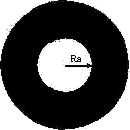
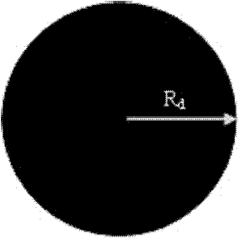
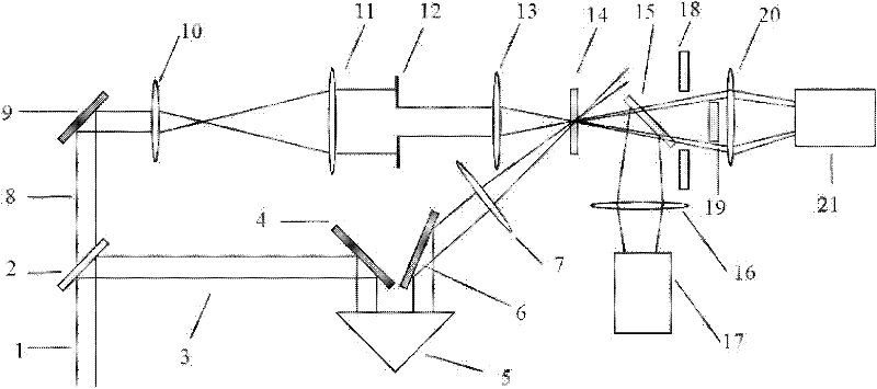
[0026] See attached image 3 As shown, a high-sensitivity measurement method for nonlinear parameters of optical functional materials is based on the detection optical path and the pumping optical path. The pumping optical path is mainly composed of two mirrors 4 and 6, a rectangular prism 5, and a convex lens 7. 5 can be translated back and forth to change the delay time of the pump light; the detection optical path is mainly composed of a reflector 9, a convex lens 10, a convex lens 11, a circular aperture 12, a convex lens 13, a beam splitter 15, a convex lens 16, and a circular diaphragm 18 ( The hole radius is R a ), circular baffle 19 (radius R d ), a convex lens 20, a first detector 17 and a second detector 21; the pump light path and the detection light path are simultaneously focused on the sample 14 to be tested.

[0027]A laser pulse 1 is split ...


PUM


Abstract

The invention discloses a phase object Z-scan-based pump-probe method, which includes the following steps: an incident laser beam is split into two beams, the beam with high intensity is pump light, the beam with low intensity is probe light, and the pump light is delayed and focused on a non-linear sample to be tested, so that the sample to be tested, which is in the ground state, generates non-linear absorption and non-linear refraction; the sample to be tested is located on the focal plane of a lens in a probe light path, a round diaphragm and a round baffle, the centers of which are superposed with the optical axis, are placed at a far-field position in the probe light path behind the sample to be tested, the emergent probe light is split into two beams by a spectroscope, one of the beams directly enters a first probe, and the other beam enters a second probe after passing through the diaphragm and the baffle. A measuring system which operates according to the method is highly sensitive and can simply process data, non-linear absorption and non-linear refraction can be measured simultaneously rather than separately, and the method has the advantages of accurate measurement results and the like.

Description

technical field [0001] The invention relates to a method for testing or analyzing materials by using optical means, in particular to a method for studying the nonlinear optical physical mechanism of materials and measuring its optical physical parameters, belonging to the field of nonlinear photonic materials and nonlinear optical information processing . Background technique [0002] The rapid development of the field of nonlinear optics is inseparable from the research on optical nonlinear materials. Finding ideal optical nonlinear materials for various applications is a very important task in the field of nonlinear optics. Materials with large optical nonlinear coefficient and ultrafast photoresponse are considered as emerging materials for manufacturing high-speed optoelectronic devices, and have great potential application value in the field of optical engineering, such as all-optical switches and other components. The study of optical nonlinear materials requires the...

Claims


Application Information

Patent Timeline
Patent Type & Authority Applications(China)
IPC IPC(8): G01N21/17
Inventor 宋瑛林杨俊义
Owner SUZHOU MICRONANO LASER PHOTON TECH CO LTD
Why Eureka
Try Eureka