
Adjustable constant-current source

A constant current source and transistor technology, applied in the direction of adjusting electrical variables, control/regulation systems, instruments, etc., can solve the problems of reduced efficiency of constant current source, failure to lift up, limit the application range of constant current source, etc., to improve the large signal The effect of response speed

Inactive Publication Date: 2012-08-22
UNIV OF ELECTRONIC SCI & TECH OF CHINA
View PDF5 Cites 5 Cited by
  • Summary
  • Abstract
  • Description
  • Claims
  • Application Information

AI Technical Summary

Problems solved by technology

Such a technical solution needs to adjust the voltage value of Vctrl to realize the dimming function. When the voltage of Vctrl is very low, that is, when the current value of the constant current source is small, the voltage drop of the power transistor will increase greatly, which will reduce the efficiency of the constant current source. ; At the same time, if this technical solution is used in the case of PWM regulation, the amplifier EA is used to modulate the current of the power transistor M0. Under a certain current premise, the PWM frequency will not be raised, which limits the application range of the constant current source. , For example, stroboscopic conditions will occur when the LED is applied to a constant current. At the same time, the external reference voltage in this scheme increases the complexity of the peripheral circuit, and due to the limitation of process conditions, most of the processes that used this scheme earlier were BJT or Under CMOS and BJT process conditions, achieving low power consumption requires other compromise considerations, such as reducing the speed of the circuit. To achieve PWM regulation, the first conduction electrode of the power transistor M0 needs to ensure sufficient withstand voltage. will not be possible

Method used


Image

  • Adjustable constant-current source
  • Adjustable constant-current source
  • Adjustable constant-current source

Examples


Embodiment Construction

[0013] The present invention will be further described below in conjunction with the accompanying drawings and specific embodiments.

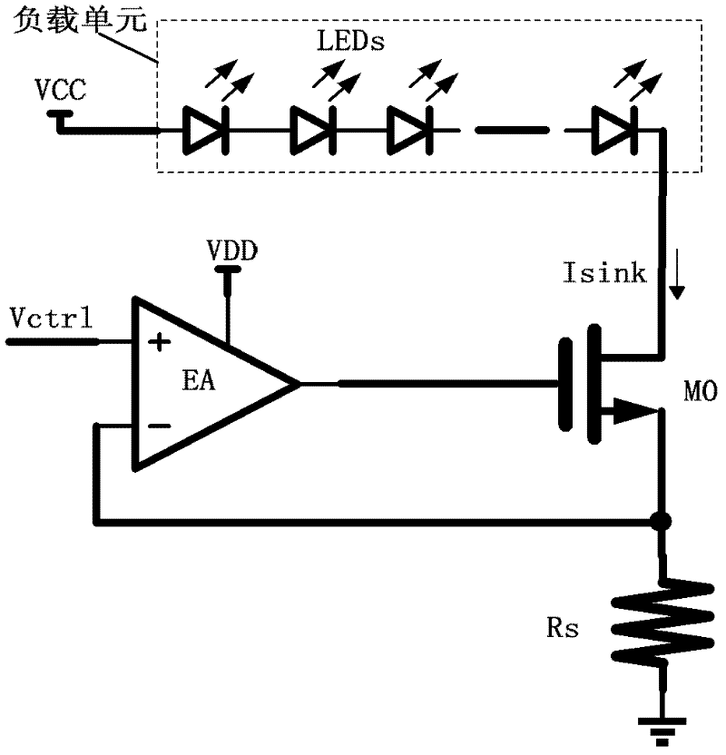
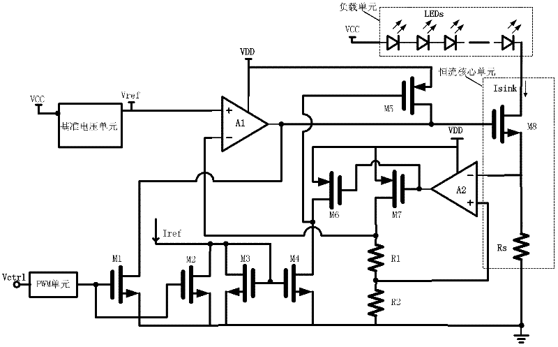
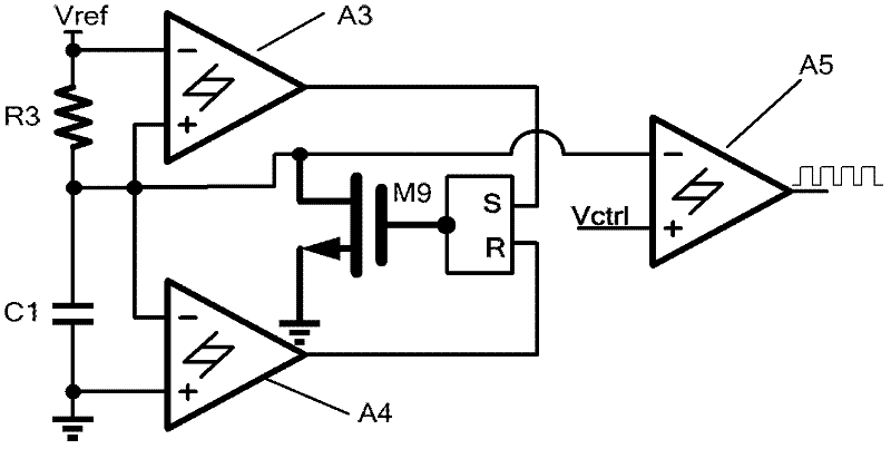
[0014] The structural block diagram of adjustable constant current source of the present invention is as figure 1 As shown, it includes: reference voltage unit, PWM unit, transistors M1, M2, M3, M4, M5, M6, M7, resistance units R1, R2, first amplifier A1 and second amplifier A2, power transistor M8 and detection resistor unit Rs, wherein the reference voltage unit is used to generate a reference voltage, and the PWM unit is used to generate a PWM signal;

[0015] The specific connection relationship is: one end of the detection resistor is grounded, the other end is connected to the second conduction pole of the N-type power transistor M8, and is connected to the inverting input end of the second amplifier A2, and the output end of the second amplifier A2 is connected to the transistor M7 The control pole of the transistor M6 is connected to t...


PUM


Abstract

The invention discloses an adjustable constant-current source, comprising a reference voltage unit, a pulse width modulation (PWM) unit, a first transistor, a second transistor, a third transistor, a fourth transistor, a fifth transistor, a sixth transistor, a seventh transistor, a first resistor unit, a second resistor unit, a first amplifier, a second amplifier, a power transistor and a sensing resistor unit. The power transistor and the sensing resistor unit constitute a basic constant-current core unit. The second amplifier amplifies a voltage, corresponding to a current, on the sensing resistor unit; the first amplifier compares an output voltage of the second amplifier with a reference voltage, and an amplified error voltage drives a gate voltage of the power transistor; the reference voltage unit provides the required reference voltage for the first amplifier; the voltage controlled PWM unit realizes a current regulation function of the constant-current source; and by establishing a low-power-consumption high-speed large-signal control path in the negative feedback of the constant-current source, the large-signal response speed of the constant-current source is improved.

Description

technical field [0001] The invention belongs to the technical field of power integration, and in particular relates to the design of a high-power linear adjustable constant current source. Background technique [0002] LED (Light Emitting Diode), light-emitting diode, is a solid-state semiconductor device that can directly convert electricity into light. Typical LED driver solutions include resistors, linear LED drivers, switching LED drivers, and innovative lighting management LED drivers. Generally speaking, depending on the size of the LED current in the application, in low-current applications of 20 to 200mA, discrete components (ie, resistors) or linear drive solutions can be used; in medium-current applications of 200 to 500mA, linear or Switch driver scheme; in high current applications greater than 500mA, the switch driver scheme is generally selected. [0003] Existing high-power linear constant current sources applied to 200 to 500mA such as figure 1 As shown, i...

Claims


Application Information

Patent Timeline
IPC IPC(8): G05F1/56
Inventor 李泽宏黄斌张仁辉吴明进任敏张金平张波
Owner UNIV OF ELECTRONIC SCI & TECH OF CHINA
Features
  • Generate Ideas
  • Intellectual Property
  • Life Sciences
  • Materials
  • Tech Scout
  • Unparalleled Data Quality
  • Higher Quality Content
  • 60% Fewer Hallucinations
Learn More