Supercharge Your Innovation With Domain-Expert AI Agents!

Shape memory alloy heat engine and energy collecting system

A heat engine and memory alloy technology, applied in the direction of machines/engines, mechanisms that generate mechanical power, mechanical equipment, etc., can solve problems such as inability to find or design heat, waste, etc.

Inactive Publication Date: 2012-08-29
GM GLOBAL TECH OPERATIONS LLC +2
View PDF6 Cites 1 Cited by
  • Summary
  • Abstract
  • Description
  • Claims
  • Application Information

AI Technical Summary

Problems solved by technology

Some of this thermal energy is waste heat, which is heat for which no beneficial use can be found or designed, and is often a wasted by-product

Method used


Image

  • Shape memory alloy heat engine and energy collecting system
  • Shape memory alloy heat engine and energy collecting system
  • Shape memory alloy heat engine and energy collecting system

Examples


Embodiment Construction

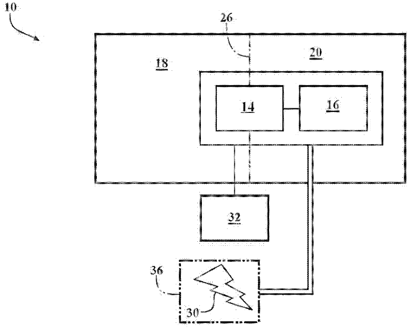
[0029] Referring to the drawings, in which like reference numerals correspond to like or similar parts wherever possible throughout the several views, in figure 1 A heat recovery system or energy harvesting system is shown in . Features and components described and shown in other figures may be incorporated into and with figure 1 used together as shown in . The illustrated energy harvesting system 10 includes a heat engine 14 and a driven component 16 .

[0030] Energy harvesting system 10 utilizes a first fluid region or thermal region 18 having a first temperature. Thermal region 18 is in thermal transfer communication with a heat source, such as waste heat, or may represent any region of relatively warmer temperatures that contributes to the operation of heat engine 14 , as described herein. The energy harvesting system 10 also utilizes a second fluid region or cold region 20 having a second temperature that is generally lower than the first temperature of the hot region...


PUM


Abstract

The invention provides a shape memory alloy heat engine and an energy collecting system. The heat engine comprises a first rotary belt wheel and a second rotary belt wheel spaced from the first rotary belt wheel. The relative part of the shape memory alloy (SMA) winding the belt wheel is arranged with a SMA belt wheel ratio. A SMA element comprises a first wire, a second wire which is in parallel with the first wire, a substrate which is connected to the first and second wires. The first and second wires contact with the belt wheel, but the substrate does not contact with the belt wheel. A timing cable winds around the relative part of the belt wheel with a timing belt wheel ratio. The SMA element converts the thermal gradient between a hot area and a cold area into mechanical energy.

Description

technical field [0001] The present invention relates generally to energy harvesting systems, and more particularly to energy harvesting systems for heat engines using shape memory alloys. Background technique [0002] Thermal energy can be generated through industrial, assembly and manufacturing processes. Motor vehicles, small equipment, and heavy equipment also generate heat. Some of this thermal energy is waste heat, which is heat for which no beneficial use can be found or designed, and is often a wasted by-product. The waste heat can be vented to the atmosphere. Combustion of transportation fuels also contributes to waste heat. Contents of the invention [0003] A heat engine is provided. The heat engine includes a first rotatable pulley and a second rotatable pulley spaced from the first rotatable pulley. A shape memory alloy (SMA) element is disposed at a first radial distance around a portion of the first rotatable pulley and at a second radial distance around...

Claims


Application Information

Patent Timeline
IPC IPC(8): F03G7/06
Inventor A.L.布朗N.L.约翰逊P.W.亚历山大J.A.肖C.B.邱吉尔A.C.基夫G.P.麦克奈特G.A.赫里拉J.W.布朗J.R.耶茨
Owner GM GLOBAL TECH OPERATIONS LLC
Features
  • R&D
  • Intellectual Property
  • Life Sciences
  • Materials
  • Tech Scout
  • Unparalleled Data Quality
  • Higher Quality Content
  • 60% Fewer Hallucinations
Learn More