
Plate-fin film type main cold liquid distributor for air separation

A technology of cold liquid and distributor, which is applied in the direction of refrigeration and liquefaction, liquefaction, solidification, etc., can solve problems such as difficult to obtain film cloth effect, main cold safety problem, excess liquid oxygen, etc., to improve the main cold safety problem, The effect of improving product quality and increasing production capacity

Inactive Publication Date: 2012-08-29
XI AN JIAOTONG UNIV +1
View PDF6 Cites 5 Cited by
  • Summary
  • Abstract
  • Description
  • Claims
  • Application Information

AI Technical Summary

Problems solved by technology

[0004] There are two main criteria to measure the structure of air separation membrane main cooling liquid distributor: one is the uniformity of liquid oxygen flow in each evaporation channel, and the other is the effect of film distribution inside a single evaporation channel. At present, for air separation membrane In terms of the structural design of the type main cooling liquid distributor, more emphasis is placed on ensuring a good film distribution effect of a single evaporation channel. However, if the liquid oxygen flow rate of each evaporation channel is uneven, it is difficult to obtain a good film distribution effect. It will affect the heat transfer performance of the main cooling, and even cause safety problems of the main cooling
For example, the uneven distribution of liquid oxygen flow in each evaporation channel may lead to excess liquid oxygen in some evaporation channels, while dry evaporation occurs in other evaporation channels with too little liquid oxygen. 2 O, etc. will precipitate on the wall of the evaporation channel, and then block the channel, causing hydrocarbons to concentrate, precipitate, and accumulate, increasing the risk of explosion

Method used


Image

  • Plate-fin film type main cold liquid distributor for air separation
  • Plate-fin film type main cold liquid distributor for air separation
  • Plate-fin film type main cold liquid distributor for air separation

Examples


Embodiment Construction

[0019] The present invention will be described in more detail below in conjunction with the accompanying drawings.

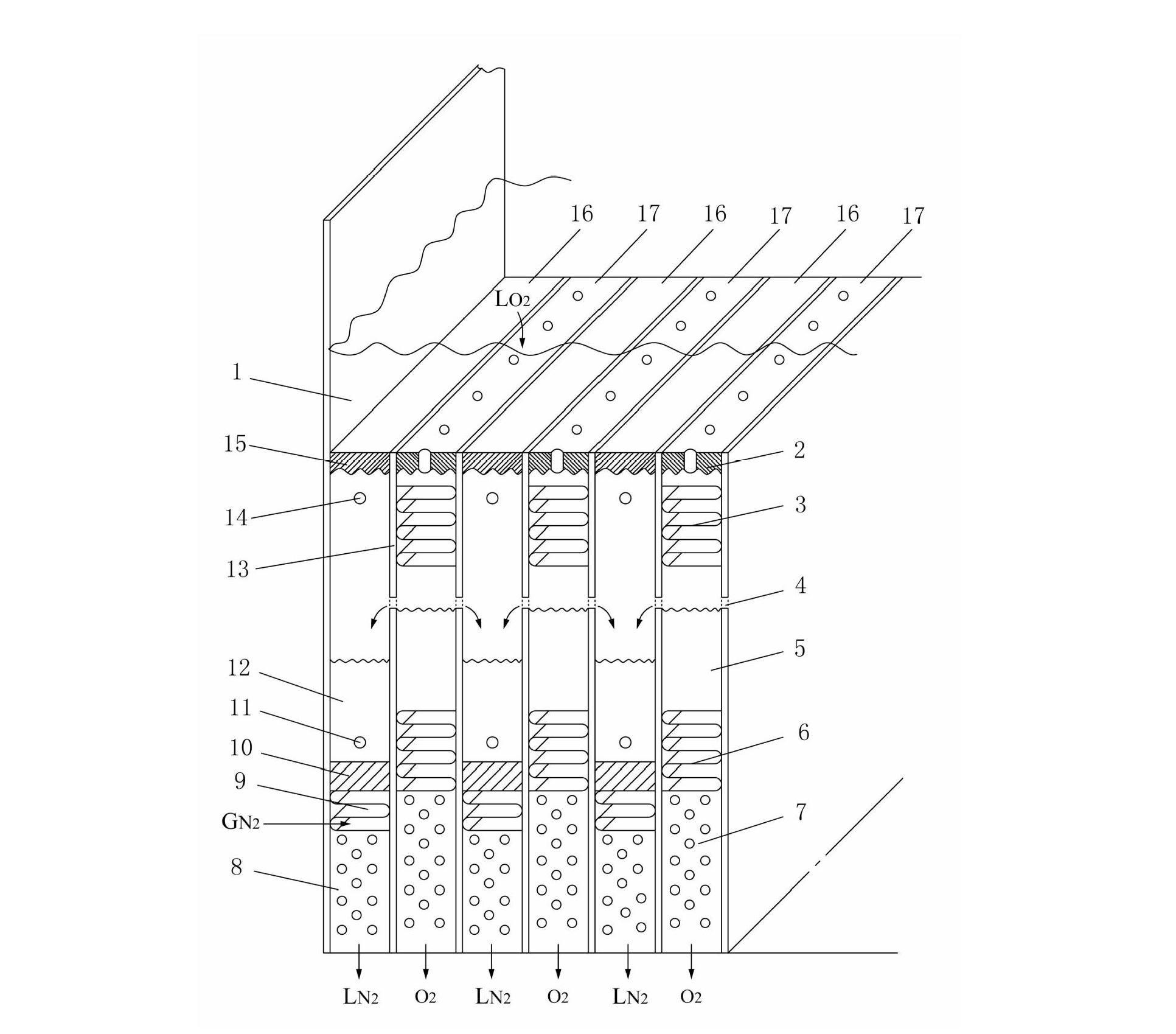
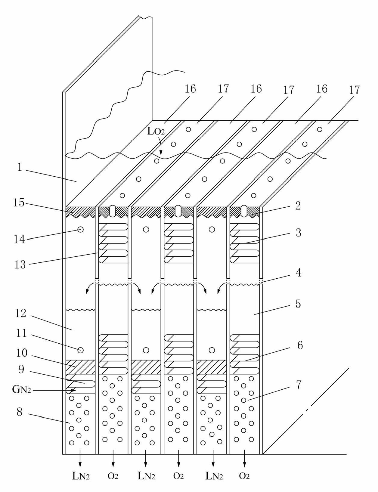
[0020] Such as figure 1 As shown, the present invention relates to an air separation plate-fin type film-type main cooling liquid distributor, comprising at least one first vertical channel 16 and at least one second vertical channel 17 arranged alternately and sequentially, the first vertical channel Channel 16 and the second vertical channel 17 are separated by vertical partitions 13 on both sides. The first vertical channel 16 includes a seal 15 that is arranged on its top and is connected to the liquid oxygen tank 1, and is arranged below the seal 15. Oxygen storage tanks 12 with preset gaps are provided with liquid outlet holes 11 on the lower side of the oxygen storage tank 12, the bottom of the oxygen storage tank 12 is connected with the seal 10, the seal 10 is connected with the deflector 9, and the deflector 9. The bottom communicates with the condens...


PUM


Abstract

The invention provides a plate-fin film type main cold liquid distributor for air separation. The plate-fin film type main cold liquid distributor comprises a pre-distribution structure, a primary distribution structure, a secondary distribution structure, an oxygen storage groove, oxygen containing grooves, overflow holes, liquid outlets and pressure equalizing holes. Primary distribution of liquid oxygen is realized by the pre-distribution structure and the primary distribution structure; re-distribution of the liquid oxygen is realized by the secondary distribution structure; a plurality of the overflow holes are uniformly arranged on separation boards at the both sides of the upper part of the oxygen storage groove along a width direction at intervals with a pre-set distance; all the overflow holes are located at the same horizontal height; the liquid outlet is arranged at one side of the bottom of each oxygen containing groove; and one pressure equalizing hole is arranged at one side at the upper part of each oxygen containing groove. With the adoption of the structure, the liquid oxygen flow of each evaporation channel can assured uniform, so as to achieve good film distribution effect inside the evaporation channels. Furthermore, the heat transmission property of a main condensing evaporator is improved, and the main cold security problems can be effectively improved.

Description

technical field [0001] The invention relates to the technical field of liquid distributors for condensing evaporators, in particular to an air separation plate-fin type film-type main cooling liquid distributor. Background technique [0002] In the rectification system of the cryogenic air separation plant, the condensing evaporator is the key heat exchange equipment connecting the upper and lower towers. Its structure and heat transfer performance have a direct impact on the energy consumption, separation efficiency and capital investment of the air separation plant. Compared with the bath-type main cooling, the heat transfer temperature difference of the membrane main cooling is small, which can reduce the pressure of the lower tower, the heat transfer coefficient K value is significantly increased, and the energy saving effect is remarkable, and the structural size of the membrane main cooling is significantly reduced. It is convenient for transportation, therefore, falli...

Claims


Application Information

Patent Timeline
Patent Type & Authority Applications(China)
IPC IPC(8): F25J3/04
Inventor 鱼剑琳贾金才宋欣徐才华马明王忠建厉彦忠刘景武马源
Owner XI AN JIAOTONG UNIV
Learn More