
Device and method for heat recovery of oil in inner floating roof storage tank

An internal floating roof storage tank and heat recovery technology, applied in steam generation methods, separation methods, chemical instruments and methods using pressure combustion, etc., can solve the problems of difficult evaporation of brine and high energy consumption

Active Publication Date: 2021-06-11
海南科技职业大学
View PDF19 Cites 0 Cited by
  • Summary
  • Abstract
  • Description
  • Claims
  • Application Information

AI Technical Summary

Problems solved by technology

However, the heat recovery method in the prior art usually directly heats the whole brine during the distillation process. If the brine is to be evaporated to a high concentration and then discharged, all the brine needs to be heated to a high concentration, and the brine It is not easy to evaporate after the concentration is increased, resulting in high energy consumption for heating to the later stage

Method used


Image

  • Device and method for heat recovery of oil in inner floating roof storage tank
  • Device and method for heat recovery of oil in inner floating roof storage tank
  • Device and method for heat recovery of oil in inner floating roof storage tank

Examples


Embodiment 1

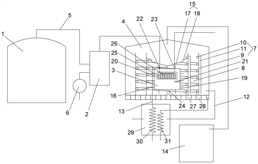
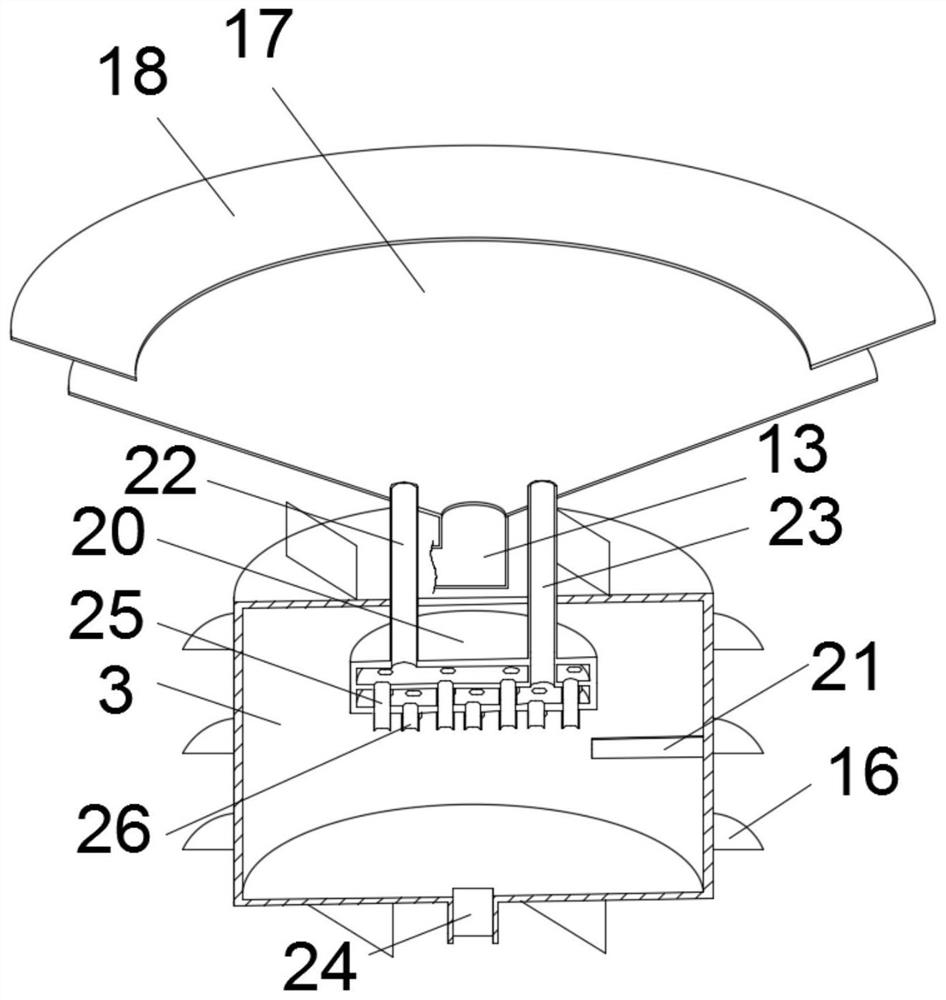
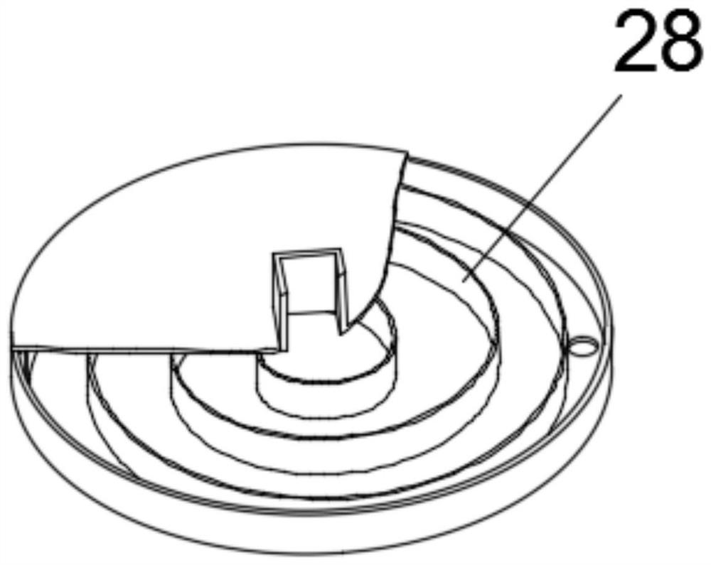
[0028] see Figure 1~4 , a heat recovery device for oil in an internal floating roof storage tank, comprising an internal floating roof storage tank 1, a buffer tank 2, a heating furnace 3 and an evaporation tank 4, the oil and gas collection pipe 5 of the internal floating roof storage tank 1 is connected to the The buffer tank 2 communicates, the buffer tank 2 communicates with the first air pump 6, the exhaust port of the buffer tank 2 communicates with the air inlet 22 of the heating furnace 3, and the heating furnace 3 is arranged in the evaporation tank 4, The evaporation tank 4 is provided with a number of diffusion barrier rings 7 surrounding the heating furnace 3, and the diffusion barrier ring 7 divides the evaporation tank 4 into several independent water storage chambers 8. The diffusion barrier ring 7 Comprising a metal ring 9, a spiral tube 10 and a vertical tube 11, the two sides of the metal ring 9 are respectively provided with the spiral tube 10 and the verti...

Embodiment 2

[0036] see Figure 5 The difference between this embodiment and Embodiment 1 is that the spiral pipe 10 and the vertical pipe 11 are embedded in the metal ring 9, the vertical pipe 11 is provided with a first one-way valve 32, and the water storage A cover 33 is slidingly provided in the chamber 8, and the cover 33 is provided with a sealing gasket 34 in contact with the inner wall of the diffusion barrier ring 7, and the cover 33 is connected to the top of the evaporation tank 4 through an electric telescopic rod 35 , the cover 33 is provided with a second one-way valve 36 . The inner and outer walls of the diffusion barrier ring 7 are smooth, and the cover 33 sliding in the water storage chamber 8 is in sealing contact with the inner wall of the diffusion barrier ring 7 . The cover 33 is connected to the top of the evaporation tank 4 through an electric telescopic rod 35. When the electric telescopic rod 35 is extended, the liquid surface is pressed down. The vertical pipe ...


PUM


Abstract

The invention discloses a device and method for heat recovery of oil in an inner floating roof storage tank, the device comprises the inner floating roof storage tank, a buffer tank, a heating furnace and an evaporation tank, an oil gas collecting pipe of the inner floating roof storage tank is communicated with the buffer tank, the buffer tank is communicated with a first air pump, an exhaust port of the buffer tank is communicated with an air inlet of the heating furnace, and the heating furnace is arranged in the evaporation tank; the evaporation tank is provided with a plurality of diffusion blocking rings surrounding the heating furnace, the diffusion blocking rings divide the evaporation tank into a plurality of mutually independent water storage cavities, each diffusion blocking ring comprises a metal ring, a spiral pipe and a vertical pipe, the spiral pipe and the vertical pipe are arranged on the two sides of the metal ring respectively, and openings are formed in the two ends of the spiral pipe and the two ends of the vertical pipe; and the top opening of the spiral pipe is communicated with the top opening of the vertical pipe, the water storage cavity located on the outermost side is communicated with the water inlet pipe, the water storage cavity located on the innermost side is communicated with the water drainage pipe, and the top of the evaporation tank is communicated with a refrigeration box through a steam pipeline. In the distillation process, all saline water is prevented from being in a high-concentration state.

Description

technical field [0001] The invention relates to the technical field of oil recovery of an inner floating roof storage tank, in particular to a device and method for heat recovery of oil from an inner floating roof storage tank. Background technique [0002] The oil and gas recovery process is a process for recovering volatile oil and gas during the use of various light hydrocarbon storage tanks. The traditional process generally uses the oil and gas volatilized from the oil in the internal floating roof storage tank after being collected through the oil and gas pipeline, and the collected oil and gas are passed through the first stage of low-temperature cooling to -15°C, and then cryogenically cooled to -75°C. The gas phase oil and gas are fully liquefied after being cryogenically cooled, and the liquid phase is collected and placed centrally. However, the recovery of oil and gas through cooling and liquefaction requires refrigeration equipment, and the operation of refriger...

Claims


Application Information

Patent Timeline
Patent Type & Authority Applications(China)
IPC IPC(8): B01D1/00B01D1/30F22B1/22F22B31/08
CPCB01D1/00B01D1/0011B01D1/30F22B1/22F22B31/08Y02P70/10
Inventor 崔秋生
Owner 海南科技职业大学
Learn More