Antenna

An antenna and antenna part technology, applied in the direction of antenna, antenna coupling, antenna components, etc., can solve the problems of low power transmission efficiency, limited power transmission efficiency, and failure to optimize the coil installation design.

Inactive Publication Date: 2012-08-29
EQUOS RES
View PDF2 Cites 20 Cited by
  • Summary
  • Abstract
  • Description
  • Claims
  • Application Information

AI Technical Summary

Problems solved by technology

However, in the coil structure described in JP-A-2009-501510, design optimization for mounting the coil on the bottom of the vehicle made of metal is not achieved, and therefore, when used in a state where the coil is mounted on the bottom of the vehicle Coils limit power transfer efficiency when
[0006] In addition, in power transmission antennas used in conventional power transmission systems, the value of Q (quality factor, quality factor), which is an important parameter for power transmission, is not always high, and the power transmission efficiency may be low

Method used


Image

  • Antenna
  • Antenna
  • Antenna

Examples


Embodiment Construction

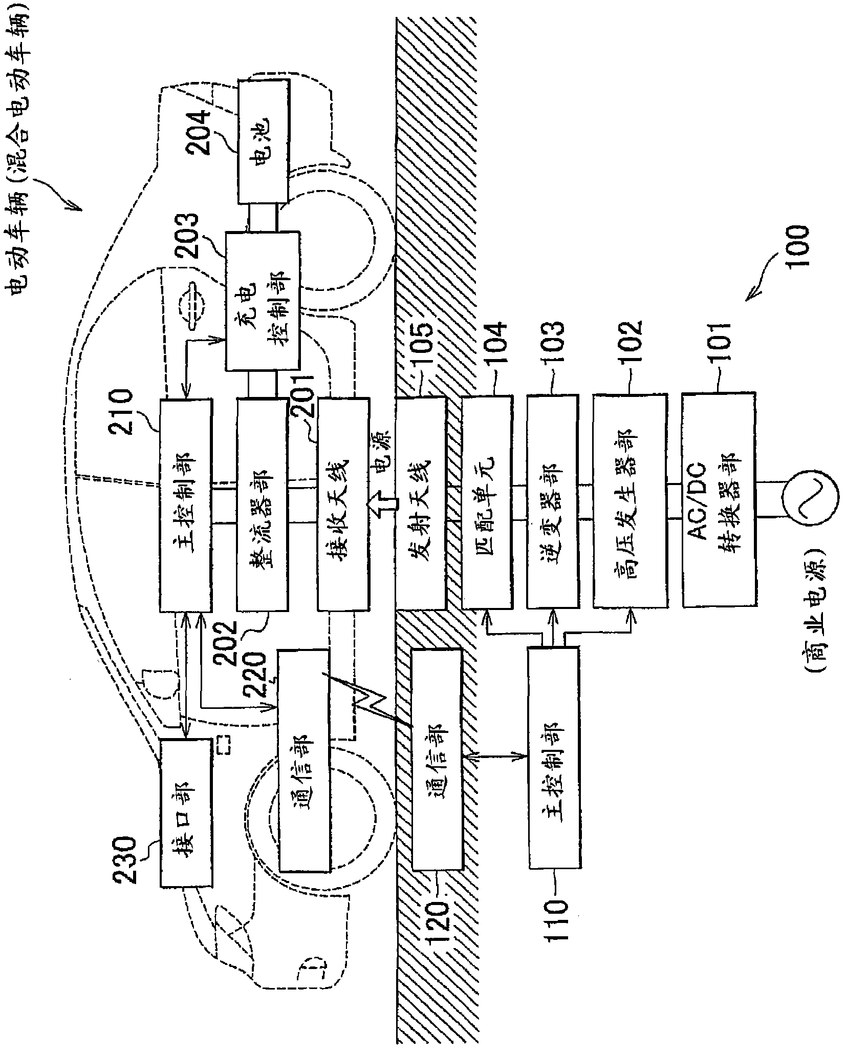
[0050] Embodiments of the present invention will be described below with reference to the accompanying drawings. figure 1 is a block diagram of a power transmission system in which an antenna according to an embodiment of the present invention is used. The antenna of the present invention can be used as a receiving antenna or a transmitting antenna, each of which is a constituent element in a power transmission system. Regarding the following embodiments, an example in which the antenna of the present invention is used as a receiving antenna is described.

[0051] A conceivable example of a power transmission system in which the antenna of the present invention is used is a system for charging vehicles such as electric vehicles (EV) and hybrid electric vehicles (HEV). In order to transmit electric power to the above-mentioned vehicles in a non-contact manner, a power transmission system is installed in a parking space where parking can be parked. The parking space used as a ...


PUM


Abstract

The invention refers to an antenna (201) that includes: a case body (260) having a bottom plate portion (261), side plate portions (262) extending from the bottom plate portion (261), and an opening portion (263) surrounded by the side plate portions (262); a magnetic resonance antenna portion (270) placed in the case body (260); and a magnetic shield body (280) disposed on a side closer to the opening portion (263) than the magnetic resonance antenna portion (270).

Description

technical field [0001] The present invention relates to an antenna used in a magnetic resonance type wireless power transmission system for transmitting / receiving power. Background technique [0002] In recent years, a technique of wirelessly transmitting electric power (electric energy) without using a power supply cable or the like has been vigorously developed. Among various types of methods for wirelessly transmitting electric power, there is a technique called a magnetic resonance method, which has received much attention. A research group at MIT proposed a magnetic resonance method in 2007, and related techniques are described in, for example, a Japanese translation of the publication of PCT Application No. 2009-501510 (JP-A-2009-501510). [0003] In the magnetic resonance wireless power transmission system, the resonance frequency of the transmitting antenna and the resonance frequency of the receiving antenna are set to be equal to each other, and an antenna with a ...

Claims


Application Information

Patent Timeline
Patent Type & Authority Applications(China)
IPC IPC(8): H01Q1/42H01Q1/36H01Q1/38H01Q1/52H02J17/00
CPCH01Q1/3225H01Q7/04H01F38/14Y02T10/7072Y02T90/14B60L53/126H01F27/36Y02T10/70H01F27/366Y02T90/12
Inventor 山川博幸伊藤泰雄佐藤健一郎下川茂则
Owner EQUOS RES
Why Eureka
Try Eureka