Needle base assembly rotating and retracting structure of safety injector

一种安全注射器、针座的技术,应用在针座组件自转回缩结构领域,能够解决注射器质量管制失败、医护人员及清洁人员刺伤、针座内缩或漏液等问题

Active Publication Date: 2012-09-05
张淑茗
View PDF4 Cites 8 Cited by
  • Summary
  • Abstract
  • Description
  • Claims
  • Application Information

AI Technical Summary

Problems solved by technology

[0002] Most of the syringes currently on the market are traditional, including injection needles without any safety devices. Not only can they be reused, but they are likely to cause drug and blood contamination. In addition, the exposed injection needles have caused medical staff and Stabbings by cleaning staff, deepening epidemic
In view of the problems existing in the above-mentioned conventional syringe structure, how to develop a syringe that can avoid secondary pollution caused by repeated use is the eager expectation of consumers, and it is also the goal and direction that related companies must work hard to develop breakthroughs
[0003] At present, the needle seat of the retractable safety syringe is designed to be fixed on the opening end of the barrel by means of frictional resistance. Such a fixed design is likely to cause the needle seat of the injection needle to fall out due to thermal expansion and contraction of the external temperature. The edge and the cylinder body tightly matched and positioned produce unexpected phenomena, such as the decrease in the degree of engagement between the needle seat and the cylinder due to a sharp rise in temperature, which causes the needle seat to shrink or leak during the injection process, or because of Sudden drop in temperature makes excessive engagement, unable to retract the injection needle and needle seat into the barrel after the injection is completed, resulting in serious failure of syringe quality control and lower yield rate

Method used


Image

  • Needle base assembly rotating and retracting structure of safety injector
  • Needle base assembly rotating and retracting structure of safety injector
  • Needle base assembly rotating and retracting structure of safety injector

Examples


Embodiment Construction

[0026] Now illustrate the present invention in conjunction with accompanying drawing and embodiment.

[0027] Description of main component symbols:

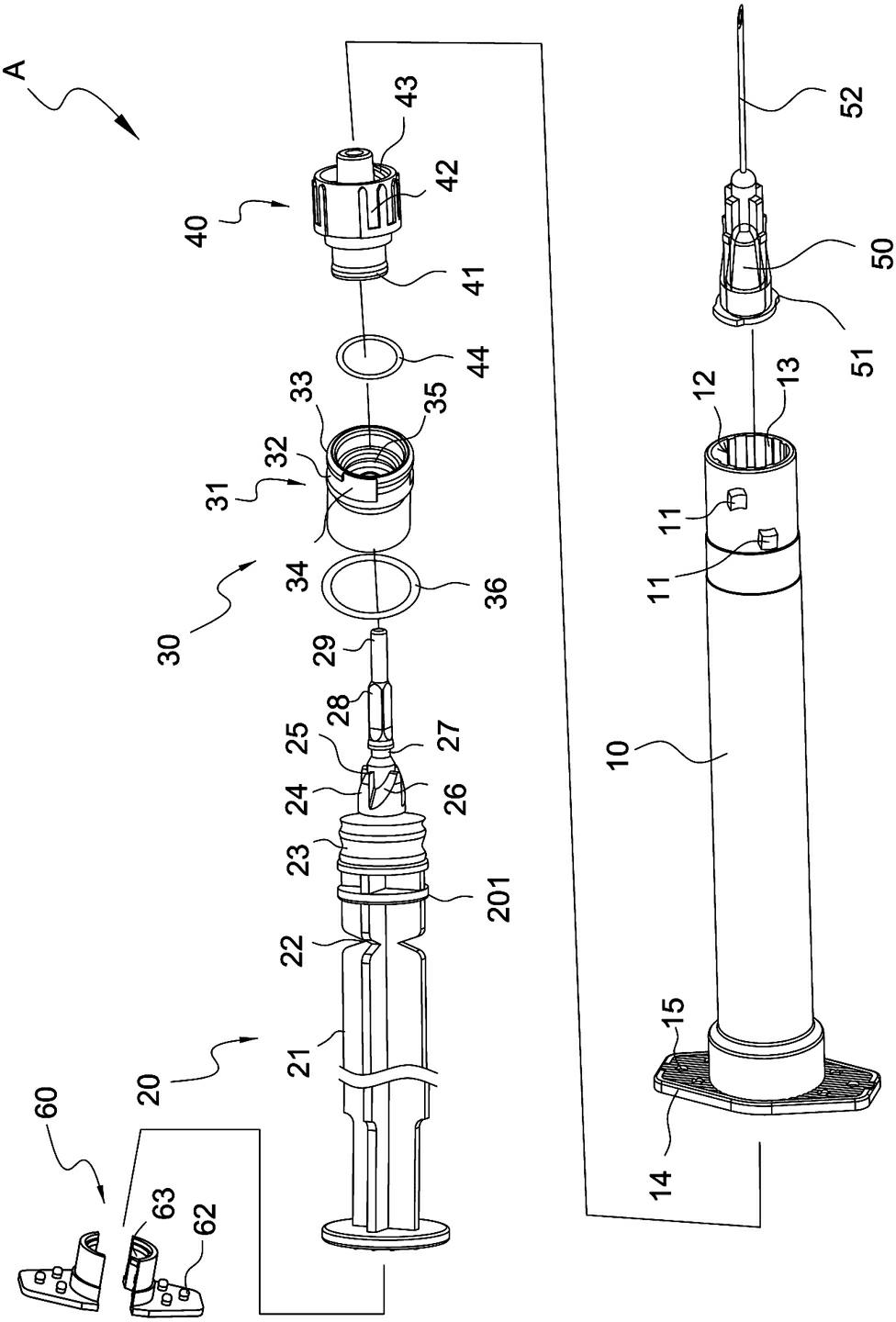
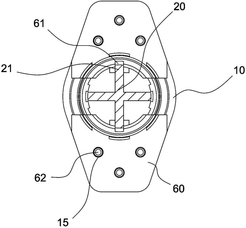
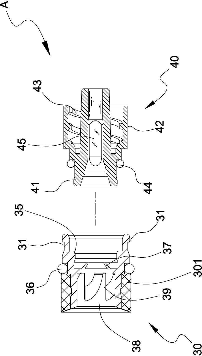
[0028] Needle seat group (A), cylinder body (10), stopper (11), chamber (12), rotation limiting piece (13), terminal end (14), group hole (15), push rod (20) , ribs (21), breaks (22), rubber plugs (23), dialing parts (24), dialing ends (25), letting grooves (26), buckle parts (27), non-circular Section (28), leading post (29), ring retaining edge (201), ring rotating piece (30), L groove (31), closed end (32), stopper (33), open end (34), Pivot part (35), sealing ring (36), embedded buckle part (37), rotation receiving part (38), guide inclined surface (39), assembly part (301), rotation limiting part (40), pivot part (41), limited rotation seat (42), assembly part (43), sealing ring (44), non-circular groove (45), injection piece (50), final assembly end (51), injection needle (52) , track clamping plate (60), limited turn g...


PUM


Abstract

The invention provides a needle base assembly rotating and retracting structure of a safety injector. The structure has the following beneficial effects: fastening grooves of the needle base assembly and fastening stops corresponding to a drum body to rotate from the limit and lock state to the non-limit and open state by virtue of automatic deflectors of a needle base assembly, so that a push rod can be rapidly embedded in the needle base assembly and positioned and presents the mode of retracting an injection needle so that the user can carry out the next retraction action, and the needle base assembly can be stably assembled and positioned at the opening end of the drum body and hardly causes the following unexpected phenomena due to the external temperature: the fastening degree between a needle base and the drum body is reduced due to temperature surge, thus causing inward retraction or leakage of the needle base in the injection process, or the needle base and the drum body are excessively fastened due to sudden temperature drop and the injection needle and the needle base can not be retracted into the drum body after injection; therefore the structure can be safely operated by the operator with one hand, improves the environment quality and achieves convenience in retraction use of the injection needle.

Description

technical field [0001] The present invention relates to a self-rotating and retracting structure of a needle seat assembly of a safety syringe, in particular to a needle seat group that can be stably fixed at the opening end of a cylinder body, and the needle seat assembly rotates through the engagement of the needle seat group and the cylinder body. resulting in innovative designs. Background technique [0002] Most of the syringes currently on the market are traditional, including injection needles without any safety devices. Not only can they be reused, but they are likely to cause drug and blood contamination. In addition, the exposed injection needles have caused medical staff and The stabbing of cleaning staff deepens the epidemic of infectious diseases. In view of the above-mentioned problems existing in the structure of conventional syringes, how to develop a syringe that can avoid secondary pollution caused by repeated use is the eager expectation of consumers, and...

Claims


Application Information

Patent Timeline
Patent Type & Authority Applications(China)
IPC IPC(8): A61M5/50A61M5/31
CPCA61M5/322A61M5/347A61M2005/323A61M2005/5073
Inventor 张淑茗
Owner 张淑茗
Why Eureka
Try Eureka