Power assembly for electric passenger car

A powertrain and electric car technology, applied to vehicle components, transmission parts, control devices, etc., can solve problems such as low machining accuracy, severe vibration, and incoordination, so as to improve machining accuracy and assembly accuracy, and move flexibly and reliably , long service life effect

Active Publication Date: 2012-09-05
DALIAN JINHUA GEARBOX MFG
View PDF8 Cites 14 Cited by
  • Summary
  • Abstract
  • Description
  • Claims
  • Application Information

AI Technical Summary

Problems solved by technology

The electric vehicle power assembly with this structure has the following disadvantages: the tower wheel in the transmission mechanism has an integral structure, and each transmission part, that is, each set of gears and each set of splines must be processed by gear shaping, which is mainly due to its structure. , the processing accuracy is relatively low, and due to structural design constraints, the gear grinding process cannot be performed after carburizing and quenching, and the gear deformation problem cannot be solved, resulting in low accuracy. It is best to control the accuracy at 8-9 levels. The biggest disadvantage is three The uniformity of the angles of the large and small gears of the tower wheels cannot be guaranteed, which makes assembly difficult or even impossible. After assembly, the meshing of each group of tower wheels and the inner ring gear is not coordinated with each other, resulting in stress. Not only the noise is loud, but also the vibration is severe during operation. The angles are inconsistent, the small teeth of the three tower wheels and the inner ring gear cannot guarantee full meshing, and the teeth are easy to break when put into use

Method used


Image

  • Power assembly for electric passenger car
  • Power assembly for electric passenger car
  • Power assembly for electric passenger car

Examples


Embodiment Construction

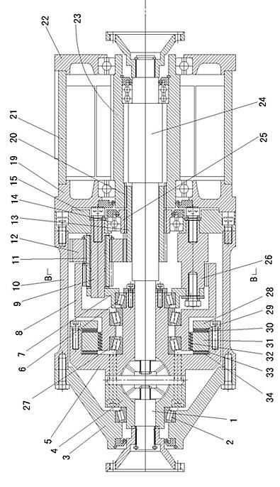
[0026] Such as Figure 1-7 As shown: the reducer housing is composed of a reducer casing 10 , a reducer left cover 3 and a reducer right cover 15 which are bolted to the reducer casing 10 . A differential housing is arranged in the reducer housing, and the differential housing is composed of a differential left housing 4 and a differential right housing 5 fixedly connected by bolts. Differential parts are arranged in the differential case, and the left half shaft 1 and the right half shaft 24 connected with the differential parts protrude to the left and right respectively.

[0027] The right side of the speed reducer housing is fixedly connected with the drive motor housing, and the drive motor housing is made up of the middle housing 21, the motor left cover 19 and the motor right cover 22 fixedly connected with the middle housing 21 bolts. The motor left cover 19 is fixedly connected with the reducer right cover 15 by bolts.

[0028] The first bearing 2 is arranged betwee...


PUM


Abstract

The invention discloses a power assembly for an electric passenger car. A differential mechanism shell is arranged inside a differential shell, the differential mechanism shell is internally provided with a differential part, a left half shaft and a right half shaft which are connected with the differential part respectively extend left and right; one side of the differential shell is fixedly connected with a driving motor shell, and a transmission mechanism is arranged between a rotor shaft in the driving motor and the differential shell; a first bearing is arranged between the left part of the differential shell and a differential left cover of the differential shell, the right part of the differential shell is connected with a support disk by virtue of a second bearing, and a support shaft is fixedly connected between a differential right cover of the differential shell and the support disk; and the transmission mechanism comprises two outer toothed sleeves and an inner toothed sleeve as well as gears which are matched with the outer toothed sleeves and the inner toothed sleeve. The power assembly for the electric passenger car disclosed by the invention has the advantages of easiness for processing, easiness for assembling, high accuracy, no noise, smoothness and reliability in operation and long service life.

Description

technical field [0001] The invention relates to a power assembly, in particular to an electric car power assembly. Background technique [0002] The invention patent application with the application number 201110327154.8 discloses a power assembly for electric vehicles. Its structure is as follows: it includes a gearbox housing, and a differential housing is connected to the gearbox housing through bearings, that is, the differential housing The box body of the gearbox can rotate relative to the gearbox, and a differential component is installed in the differential housing, and the differential component is connected with a left half shaft stretching out to the left and a right half shaft stretching out to the right. A drive motor is fixedly connected to the side cover of the gearbox housing, and the rotor shaft of the drive motor is tubular and is sleeved on the outside of the half shaft on this side. There is a transmission mechanism between the rotor shaft and the differ...

Claims


Application Information

Patent Timeline
Patent Type & Authority Applications(China)
IPC IPC(8): B60K17/06B60K17/16F16H57/037F16H57/023
Inventor 陈晓金
Owner DALIAN JINHUA GEARBOX MFG
Why Eureka
Try Eureka