Binder dent gauge protection underreamer with elastic floating sleeve

A floating sleeve and reamer technology, applied in casing, construction, earth-moving drilling, etc., can solve problems such as increased heat generation, failure to work properly, wheel drop accidents, etc., to reduce friction coefficient and prolong service life. , the effect of reducing heat

Inactive Publication Date: 2012-09-05
TIANJIN LILIN BIT
View PDF0 Cites 0 Cited by
  • Summary
  • Abstract
  • Description
  • Claims
  • Application Information

AI Technical Summary

Problems solved by technology

After the seal fails, the mud carries debris and other impurities into the bearing seal cavity, the bearing will be severely worn and cannot work normally, and sometimes a wheel accident may occur
At present, technicians have greatly improved the sealing performance of the bearing by changing the structure of the reamer, such as removing the back of the palm and replacing the back of the palm with a cone seat in the gear assembly. There is no back of the palm and the tip of the palm, so the hole wall is avoided. The damage caused by rock chips and sand at the bottom indirectly protects the sealing system of the bearing of the cone assembly. However, due to the sliding friction between the large shaft of the cone seat and the inner hole of the corresponding cone, when the cone runs at high speed , with the addition of drilling pressure and the reaction force of the ground to the drill bit, a great friction force is generated between the cone and the bearing of the cone, which leads to the continuous increase of its calorific value, resulting in serious wear and tear, which seriously affects the drill bit. service life

Method used


Image

  • Binder dent gauge protection underreamer with elastic floating sleeve
  • Binder dent gauge protection underreamer with elastic floating sleeve
  • Binder dent gauge protection underreamer with elastic floating sleeve

Examples


Embodiment Construction

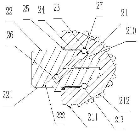
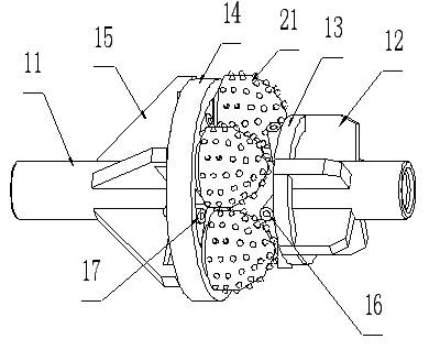
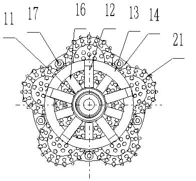
[0019] The specific implementation manner of the present invention will be described in detail below in conjunction with the accompanying drawings and preferred embodiments. As shown in the figure, a side tooth gauge diameter reamer with an elastic floating sleeve includes a reamer body and a cone assembly composed of a cone 21 and a cone seat 22. The reamer body is mainly composed of Both ends are provided with drill pipe joint thread 110 body mandrel 11, ring plate 13, main board 14, front guide plate 12, rear guide plate 15, radial water pipe 16, inclined water pipe 17, the front guide plate, ring plate , the main board, and the rear guide plate are fixedly connected to the mandrel of the body in sequence from front to back, and no less than three cone seat mounting holes 140 are evenly distributed on the upper circumference of the main board, and the radial water pipes are placed on the front guide plate The rear and radially penetrate the mandrel of the body. The inclined...


PUM


Abstract

The invention belongs to a geology drilling tool, and particularly relates to a binder dent gauge protection underreamer with an elastic floating sleeve. The binder dent gauge protection underreamer is mainly composed of an underreamer body and a cone assembly which comprises a cone base and a cone, wherein the cone base and the underreamer body are fixedly connected into a whole, and grooves are formed in corresponding positions on the cone or a pinch wheel base respectively; a lock groove is closed so as to form a locking steel ball runway groove, a locking steel ball is placed in the locking steel ball runway groove, the cone is sleeved on the cone base and is axially locked with the cone base through the locking steel ball; and the underreamer is characterized in that a large shaft of the cone base is sleeved on the elastic floating sleeve, and the elastic floating sleeve is in sliding fit with the inner hole of the cone at the corresponding position. The underreamer provided by the invention has the beneficial effects that the elastic floating sleeve can float between the cone and a cone base bearing, the addition of relative movement speed of parts inside and outside the sleeve is equal to the relative rotational speed between the cone and the cone base; and the relative movement speed of each friction surface is reduced by half, so that the unnecessary abrasion is avoided, the heat productivity is reduced, and the service life of the underreamer is prolonged.

Description

technical field [0001] The invention belongs to geological drilling tools, in particular to a side-tooth diameter-gauge reamer with an elastic floating sleeve. Background technique [0002] With the development of the oil drilling industry, the service life of the reamer, one of the main drilling tools, plays a vital role in the construction. The main structure of the cutting unit of the reamer is the cone and the palm part. The sealing effect of the bearing formed by the cone hole and the palm shaft directly affects the service life of the reamer. A hole reamer of the prior art, the back of the palm of the tooth is close to the wall of the hole to be reamed. Since the reaming operation of the reamer is generally a horizontal or near-horizontal operation, a large amount of sand and rock debris are deposited in the lower part of the tunnel, and the grinding and erosion of the back of the palm are very serious. When the back of the palm is worn to a certain extent, It will d...

Claims


Application Information

Patent Timeline
Patent Type & Authority Applications(China)
IPC IPC(8): E21B10/30E21B10/22E21B10/52E21B10/25
Inventor 刘子洲
Owner TIANJIN LILIN BIT
Why Eureka
Try Eureka