Spindle bearing lubricating system for wind driven generator

A technology for wind turbines and main shaft bearings, applied in the field of lubrication systems, which can solve the problems of large space occupation, poor grease fluidity, and reduced grease lubrication functions, etc., to achieve the effects of improving lubrication effects, improving lubrication quality, and prolonging service life

Inactive Publication Date: 2012-09-05
GUANGDONG MINGYANG WIND POWER IND GRP CO LTD
View PDF6 Cites 15 Cited by
  • Summary
  • Abstract
  • Description
  • Claims
  • Application Information

AI Technical Summary

Problems solved by technology

[0002] The main shaft of the wind turbine is lubricated by the independent bearing housing mostly with grease. The bearing itself does not have a sealing cover, and the grease is not easy to preserve. The low speed and heavy load of the fan main shaft is not easy to form an oil film. It is difficult to replace the lubricant and clean the bearing. The operating temperature range is small, and the fluidity of the grease is very poor at low temperature. Below -5°C, the grease cannot flow, and the grease squeezed out from the rolling elements of the bearing will not return to the raceway to participate in lubrication. For the automatic lubrication device, when the temperature is below -5°C, the injected grease can only lubricate near the injection point, it is difficult to realize the lack of grease alarm device, it is difficult to discharge waste grease during grease lubrication, and new grease passes through Half a year's operation will become waste grease. If it cannot be removed in time, the residual waste grease will pollute the newly added grease, and the newly added grease will quickly become waste grease, and the wear of the bearing during operation If the debris cannot be discharged in time, the wear debris remaining in the grease will greatly reduce the lubricating function of the grease and have a great impact on the life of the bearing. The traditional bearing lubrication system uses an integrated bearing seat, which occupies a large space and is inconvenient to operate.

Method used


Image

  • Spindle bearing lubricating system for wind driven generator
  • Spindle bearing lubricating system for wind driven generator

Examples


Embodiment Construction

[0018] Embodiments of the present invention are described in further detail below in conjunction with the accompanying drawings:

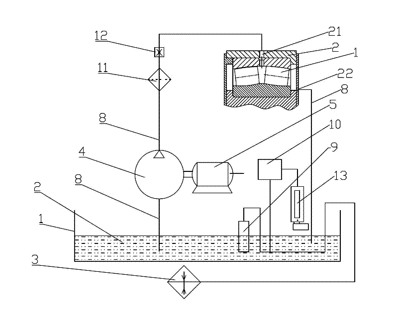
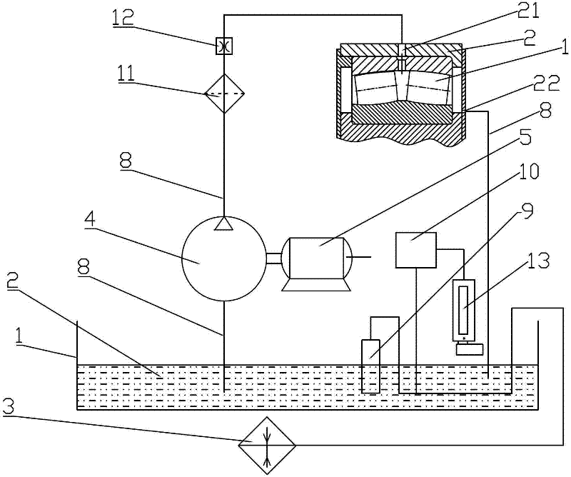
[0019] Such as figure 1 As shown, a wind turbine main shaft bearing lubrication system includes a main shaft bearing 1, a bearing seat 2 sleeved on the main shaft bearing 1, an oil inlet hole 21 and an oil return hole 22 are arranged on the bearing seat 2, and the oil inlet hole 21 The oil pump 4 is connected to the oil pump 4 through the oil delivery pipe 31. The oil pump 4 is connected to the oil tank 5 through the oil delivery pipe 32. The oil return hole 22 is connected to one end of the oil delivery pipe 33. The other end of the oil delivery pipe 33 extends into the oil tank 5. Through the lubrication system of the main shaft bearing of the wind power generator, the oil tank The lubricating oil 12 in 5 can be recycled to improve the lubricating effect and reduce the pollution to the environment.

[0020] In the present invention, a filter 6 i...


PUM


Abstract

The invention relates to a spindle bearing lubricating system for a wind driven generator. The spindle bearing lubricating system comprises a spindle bearing (1) and a bearing base (2) sleeved on the spindle bearing (1), wherein an oil inlet (21) and an oil return hole (22) are arranged on the bearing base (2); the oil inlet (21) is connected with an oil pump (4) through an oil transmission pipe (31); the oil pump (4) is connected with an oil tank (5) through an oil transmission pipe (32); the oil return hole (22) is connected with one end of an oil transmission pipe (33); and the other end of the oil transmission pipe (33) extends into the oil tank (5). With the adoption of the spindle bearing lubricating system for the wind driven generator, lubrication oil can be circularly used and flows back into the oil tank after a bearing is lubricated, so as to achieve sufficient lubrication and reduce pollution to an environment. A heater is arranged in the oil tank, so that when an environment temperature is lower, the heater heats the lubrication oil to ensure that the lubricating system normally operates; and when an oil level reaches an alarming value, the spindle bearing lubricating system can automatically alarm, so that the service life of the bearing is prolonged.

Description

【Technical field】 [0001] The invention relates to a lubricating system, in particular to a lubricating system for a main shaft bearing of a wind power generator. 【Background technique】 [0002] The main shaft of the wind turbine is lubricated by the independent bearing housing mostly with grease. The bearing itself does not have a sealing cover, and the grease is not easy to preserve. The low speed and heavy load of the fan main shaft is not easy to form an oil film. It is difficult to replace the lubricant and clean the bearing. The operating temperature range is small, and the fluidity of the grease is very poor at low temperature. Below -5°C, the grease cannot flow, and the grease squeezed out from the rolling elements of the bearing will not return to the raceway to participate in lubrication. For the automatic lubrication device, when the temperature is below -5°C, the injected grease can only lubricate near the injection point, it is difficult to realize the lack of gr...

Claims


Application Information

Patent Timeline
Patent Type & Authority Applications(China)
IPC IPC(8): F16N7/40F16N39/06F16N39/04F16N29/04F03D11/00F03D80/70
CPCY02E10/72
Inventor 陈建民
Owner GUANGDONG MINGYANG WIND POWER IND GRP CO LTD
Why Eureka
Try Eureka