Electronic handwriting screen
An electronic hand and bottom electrode technology, applied in electrical digital data processing, instruments, computing, etc., can solve the problems of low battery life, high manufacturing costs, high costs of touch modules and display screens, and achieve erasing operations with low costs. , the effect of improving convenience
- Summary
- Abstract
- Description
- Claims
- Application Information
AI Technical Summary
Problems solved by technology
Method used
Image

Examples
Embodiment 1
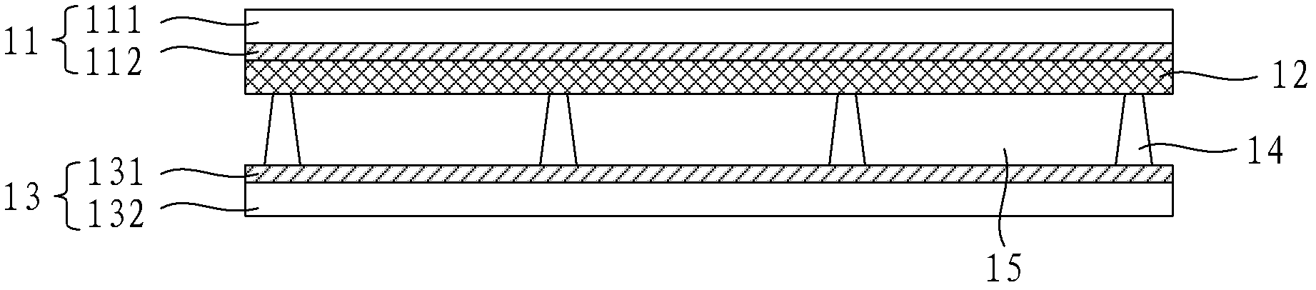
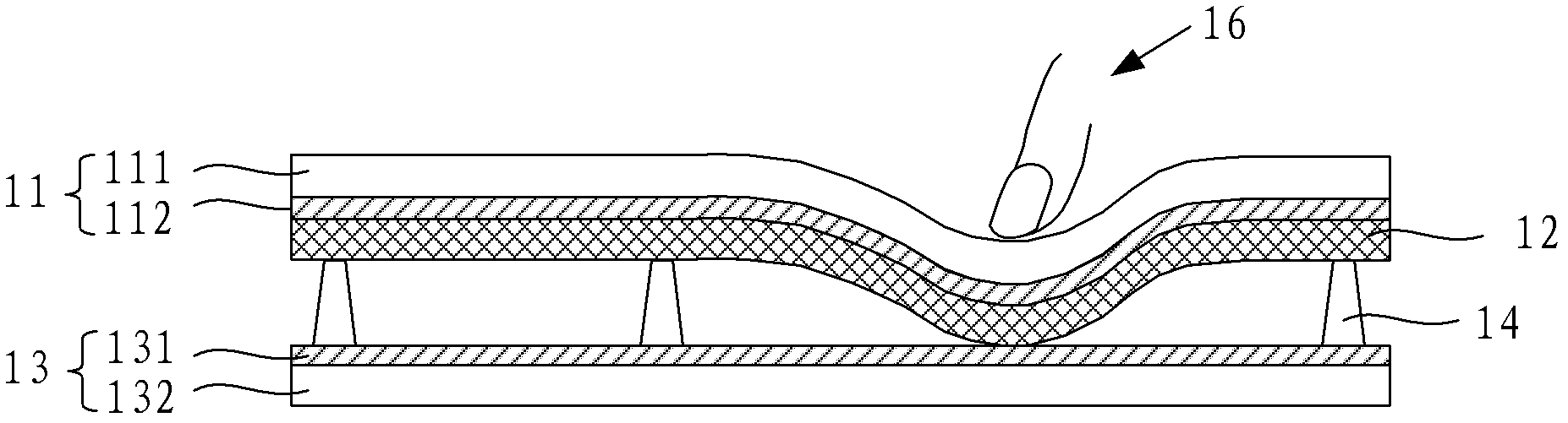
[0026] This embodiment provides an electronic handwriting screen, such as figure 1 As shown, the electronic handwriting screen includes: a top electrode 11 , an electrophoretic display function film 12 and a bottom electrode 13 . Wherein, the electrophoretic display function film 12 is disposed between the top electrode 11 and the bottom electrode 13 . In addition, an insulating spacer 14 is provided between the electrophoretic display functional film 12 and the bottom electrode 13 , and the insulating spacer 14 is used to form a gap 15 between the electrophoretic display functional film 12 and the bottom electrode 13 .
[0027] The top electrode 11 is composed of a first substrate 111 and a first ITO (Indium Tin Oxides, indium tin oxide) 112 coated on the surface thereof. The bottom electrode 13 is composed of a second substrate 131 and a second ITO 132 coated on its surface. Such as figure 1 As shown, on the second substrate 131 , the second ITO 132 , the insulating spa...
Embodiment 2
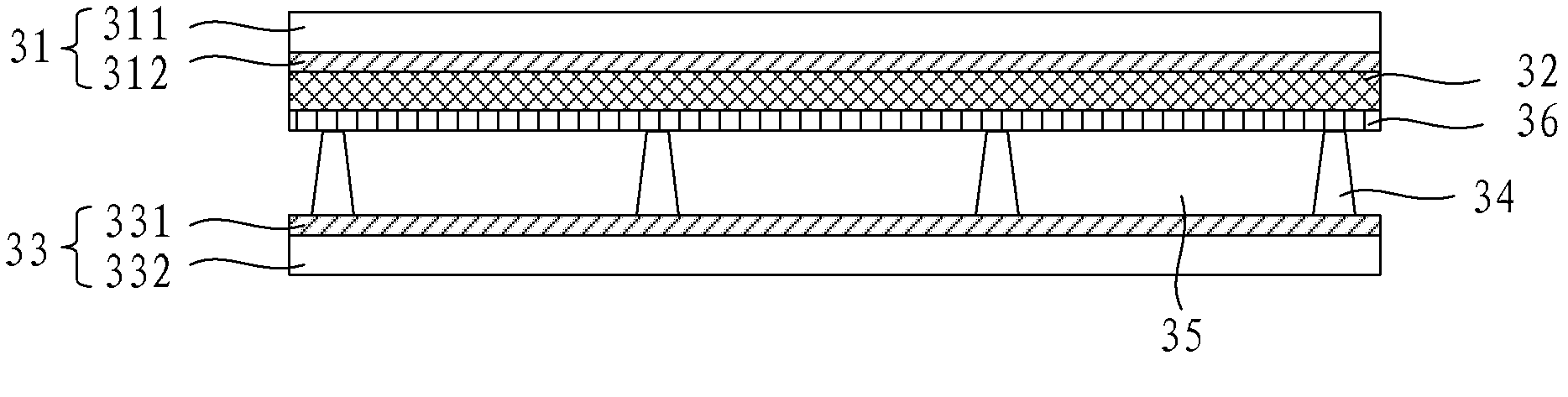
[0049] This embodiment provides an electronic handwriting screen, such as image 3 As shown, the electronic handwriting screen includes: a top electrode 31 , an electrophoretic display function film 32 and a bottom electrode 33 . Wherein, the electrophoretic display function film 32 is disposed between the top electrode 31 and the bottom electrode 33 . In addition, an insulating spacer 34 is provided between the electrophoretic display functional film 32 and the bottom electrode 33 , and the insulating spacer 34 is used to form a gap 35 between the electrophoretic display functional film 32 and the bottom electrode 33 .
[0050] Different from the electronic handwriting screen provided in Embodiment 1, the electronic handwriting screen provided in this embodiment further includes a semiconductive film 36, which is arranged on the electrophoretic display functional film 32 adjacent to the insulating spacer element 34. On the surface of the side, the thickness of the semiconduc...
Embodiment 3
[0059] This embodiment provides an electronic handwriting screen, such as Figure 4 As shown, the electronic handwriting screen includes: a top electrode 41 , an electrophoretic display function film 42 and a bottom electrode 43 . Wherein, the electrophoretic display function film 42 is disposed between the top electrode 41 and the bottom electrode 43 . In addition, an insulating spacer 44 is provided between the electrophoretic display functional film 42 and the bottom electrode 43 , and the insulating spacer 44 is used to form a gap 45 between the electrophoretic display functional film 42 and the bottom electrode 43 .
[0060] The top electrode 41 is composed of a first substrate 411 and a first ITO 412 coated on its surface. The bottom electrode 43 is composed of a second substrate 431 and a second ITO 432 coated on its surface. Wherein, the material of the first and second substrates can be but not limited to PET.
[0061] Different from the electronic handwriting scre...
PUM
| Property | Measurement | Unit |
|---|---|---|
| Height | aaaaa | aaaaa |
| Thickness | aaaaa | aaaaa |
| Bar width | aaaaa | aaaaa |
Abstract
Description
Claims
Application Information
PatSnap Eureka turns technology decisions into work you can execute. Powered by our Innovation Knowledge Graph, it runs expert workflows across engineering, life sciences, materials and intellectual property. Get your review-ready output in minutes.


