Multicolour OLED (organic light-emitting diode), multicolour OLED unit and display device
A display device and color light technology, which is applied in the direction of electrical components, electric solid-state devices, semiconductor devices, etc., can solve the problems of multi-color OLED structure and process complexity, poor performance, etc., and achieve the effect of simple equipment requirements and reduced process steps
- Summary
- Abstract
- Description
- Claims
- Application Information
AI Technical Summary
Problems solved by technology
Method used
Image

Examples
Embodiment 1
[0034] This embodiment 1 is a preferred embodiment of the present invention, which is only used to describe in detail a preferred structure of the multi-color OLED unit of the present invention. Those skilled in the art should be able to realize that the following description is only one This preferred embodiment is not a necessary embodiment of the present invention. Any known materials or processes used in the manufacture of OLED basic components in the prior art can be applied to the present invention to solve its technical problems, and therefore, on the basis of any known materials or processes performed by those skilled in the art without creative labor All implementations should fall within the protection scope of the present invention.
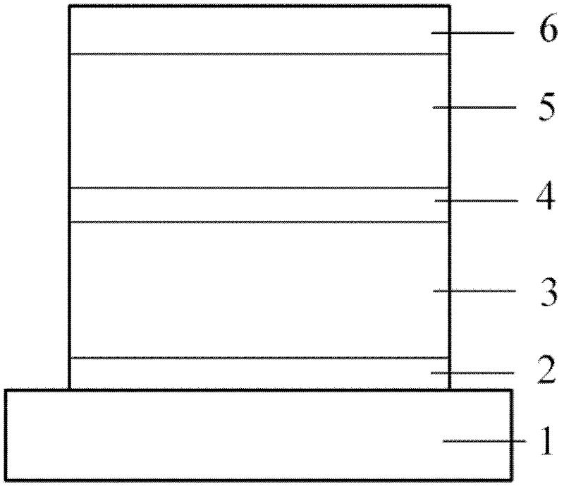
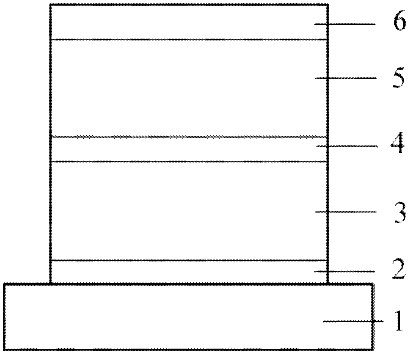
[0035] Specifically, the structure of the multi-color OLED unit of Example 1 is as figure 1 As shown, they are composed of a substrate 1, a first electrode 2, a first OLED 3, a second electrode 4, a second OLED 5, and a third electrode 6...
Embodiment 2
[0044] The multi-color OLED unit in the second embodiment also constitutes a top-emitting device unit, and its structure is basically the same as that of the first embodiment. figure 1 Shown. The difference is that in the present embodiment 2, the first OLED 3 is an inverted OLED device, and the second OLED 5 is a common top-emitting device. Therefore, the second electrode 4 is a common anode, and the first electrode 2 and the third electrode 6 are cathodes. and:
[0045] The first electrode 2 is a cathode with good reflectivity and opacity; it is a metal, or an alloy of several metals, or a combination of a metal, an alloy, and an oxide with good conductivity, such as: Al, Ag:Al, Ag : Mg, Ag / Al, Ag / Mg, ITO / Al, ITO / Ag:Al, ITO / Ag:Mg, ITO / Ag / Al, ITO / Ag / Mg, etc. This electrode needs to have good conductivity, good reflectivity, good chemical and morphological stability, and a work function that matches the second organic layer of the first OLED 3 (preferably, the work function is...
Embodiment 3
[0049] The structure of the multi-color OLED unit in Example 3 is also figure 1 As shown, the difference is that it changes the two solutions of Embodiment 1 and Embodiment 2 into a bottom emitting device unit, that is, a transparent substrate 1 and a first electrode 2 connected to the substrate 1 also need to be It is transparent, and the third electrode 6 needs to be an electrode with good reflectivity.
[0050] Specifically, when the first electrode 2 is an anode, it needs to be a transparent anode, which can be a metal, or an alloy of several metals, or an oxide with a good conductive function, or a metal, an alloy, and an oxide with a good conductive function. Combinations, such as: Ag, Au, Pd, Pt, ITO, IZO, Ag:Au, Ag:Pd, Ag:Pt, Al:Au, Al:Pd, Al:Pt, Ag:Au, Ag / Pd, Ag / Pt, Ag / ITO, Ag / IZO, Al / Au, Al / Pd, Al / Pt, Al / ITO, Al / IZO, Ag:Pd / ITO, Ag:Pt / ITO, Al:Au / ITO, Al: Pd / ITO, Al:Pt / ITO, Ag:Au / ITO, Ag:Pd / IZO, Ag:Pt / IZO, Al:Au / IZO, Al:Pd / IZO, Al:Pt / IZO, Ag:Au / IZO etc. This electro...
PUM
 Abstract
Description
Claims
Application Information
 - Generate Ideas
- Intellectual Property
- Life Sciences
- Materials
- Tech Scout
- Unparalleled Data Quality
- Higher Quality Content
- 60% Fewer Hallucinations
Browse by: Latest US Patents, China's latest patents, Technical Efficacy Thesaurus, Application Domain, Technology Topic, Popular Technical Reports.
© 2025 PatSnap. All rights reserved.Legal|Privacy policy|Modern Slavery Act Transparency Statement|Sitemap|About US| Contact US: help@patsnap.com