Supercharge Your Innovation With Domain-Expert AI Agents!

Stainless steel corrugated oil storage tank and manufacturing process thereof

A manufacturing process and oil storage tank technology, which is applied in the direction of manufacturing tools, metal processing equipment, welding equipment, etc., can solve the unfavorable transportation and installation of transformer oil storage tanks, low space utilization of oil storage tanks, and large volume of transformer oil storage tanks And other problems, to achieve the effect of beautiful appearance, high utilization rate, convenient use and maintenance

Inactive Publication Date: 2012-09-12
JIANGSU HENGFENG BELLOWS
View PDF1 Cites 3 Cited by
  • Summary
  • Abstract
  • Description
  • Claims
  • Application Information

AI Technical Summary

Problems solved by technology

The metal bellows installed in the oil conservator of the above invention is a circular pipe-shaped bellows, while the transformer oil conservator is usually a cuboid structure, which will result in a smaller volume of the metal bellows, or a larger volume of the transformer oil conservator. That is, the space utilization rate of the oil conservator is low, which is not conducive to the transportation and installation of the transformer oil conservator, and its manufacturing and installation costs are relatively high

Method used


Image

  • Stainless steel corrugated oil storage tank and manufacturing process thereof
  • Stainless steel corrugated oil storage tank and manufacturing process thereof
  • Stainless steel corrugated oil storage tank and manufacturing process thereof

Examples


Embodiment Construction

[0033] The manufacturing process of the stainless steel corrugated oil storage tank comprises the following steps:

[0034] (1) Cutting, cutting the stainless steel plate according to the design size;

[0035] (2) Welding, using an automatic longitudinal seam welding machine to weld the blanked stainless steel plate into a circular tube. This step requires smooth and smooth welds;

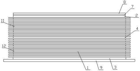
[0036] (3) Expanding the wave, the circular tube is made into a bellows by an automatic hydraulic expanding machine. This step requires the inside of the bellows to be clean and free of garbage;

[0037] (4) Shaping and cleaning, use a shaping machine to make the wave distance and wave height of the bellows uniform, and clean the oil and dust inside the wave crest of the bellows. This step requires no wave height and oblique bending;

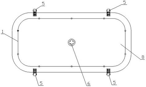
[0038] (5) Pulling, pulling the bellows into a rectangular structure, knocking the two ends of the bellows into a flat connection surface, and making the connection...


PUM

PropertyMeasurementUnit
thicknessaaaaaaaaaa
thicknessaaaaaaaaaa

Abstract

The invention relates to a stainless steel corrugated oil storage tank and a manufacturing process thereof. The process comprises the following steps: (1) blanking; (2) welding stainless steel plates to form circular pipes; (3) corrugating; (4) shaping; (5) drawing corrugated pipes into a rectangular shape; (6) compressing; (7) stacking the two corrugated pipes together and well welding; (8) welding the connecting surfaces of the two corrugated pipes; (9) welding an upper panel and a lower panel; and (10) performing leakage testing. The stainless steel corrugated oil storage tank is formed by welding at least two joints of the corrugated pipes, the upper ends and lower ends of the corrugated pipes are respectively hermetically connected with the upper panel and the lower panel, and an exhaust pipe interface is arranged on the upper panel; and pulleys are arranged on the two sides of a core body, and a counterweight block is arranged on the upper surface of the core body. The pulleys are arranged on the two sides of the stainless steel corrugated oil storage tank disclosed by the invention, and when the stainless steel corrugated oil storage tank is mounted, the pulleys can be matched with tracks for use, so that the stability of the core body is good when the core body extends and contracts up and down, the core body can be kept vertical longitudinally during long-term use, and the phenomena of inverted waves and damages caused by pulling can be avoided. The stainless steel corrugated oil storage tank disclosed by the invention has the advantages of high space utilization rate, aesthetic and elegant appearance, low manufacturing and mounting cost, and safety and reliability in working.

Description

technical field [0001] The invention relates to a power transformer device, in particular to a stainless steel corrugated oil storage tank for a transformer and a production process for manufacturing the stainless steel corrugated oil storage tank. [0002] Background technique [0003] On May 2, 2001, Chinese patent CN1065351C disclosed the invention patent of "Bellows type transformer oil conservator". This patent mainly installs a metal bellows in the transformer oil conservator, uses the change in the internal volume of the elastic element when it expands and contracts to realize the volume compensation of the transformer oil, and welds the bellows assembly on the bottom surface of the oil conservator shell , the oil inlet pipe is fixed on the bellows assembly. The metal bellows installed in the oil conservator of the above invention is a circular pipe-shaped bellows, while the transformer oil conservator is usually a cuboid structure, which will result in a smaller vo...

Claims


Application Information

Patent Timeline
Patent Type & Authority Applications(China)
IPC IPC(8): B23P15/00B23K31/02H01F27/14
Inventor 蒋峰梅桂林蒋爱琴
Owner JIANGSU HENGFENG BELLOWS
Features
  • R&D
  • Intellectual Property
  • Life Sciences
  • Materials
  • Tech Scout
  • Unparalleled Data Quality
  • Higher Quality Content
  • 60% Fewer Hallucinations
Learn More