Vertical grouting flue manufacturing equipment
A technology for vertical grouting flue and manufacturing equipment, which is applied in the direction of manufacturing tools, ceramic molding machines, molds, etc. It can solve the difficulty of accurately grasping the accuracy of mortar solidification time, increase the resistance coefficient of exhaust gas, and the inner wall of the flue is not smooth enough, etc. problem, to achieve the effect of uniform gel distribution, saving raw and auxiliary materials, and reducing labor intensity of workers
- Summary
- Abstract
- Description
- Claims
- Application Information
AI Technical Summary
Problems solved by technology
Method used
Image
Examples
Embodiment 1
[0032] Embodiment 1 Die set
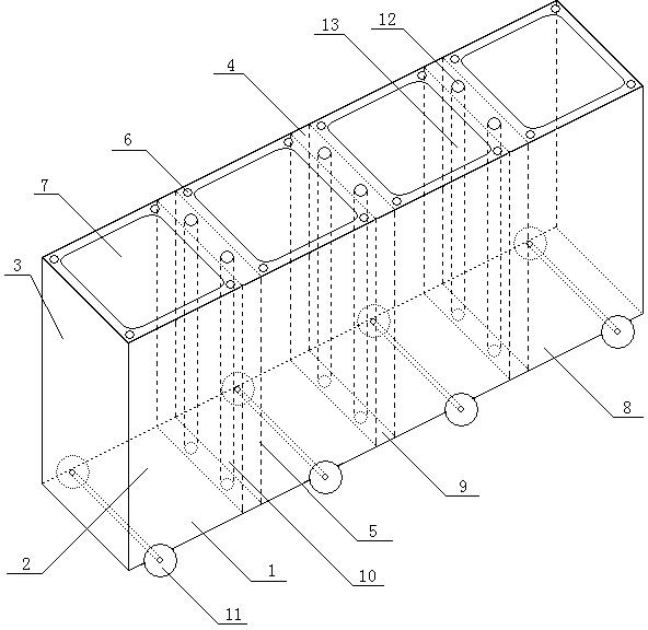
[0033] Vertical grouting flue manufacturing equipment, including mold sets and inner cavity moulds. Die set such as figure 1 As shown, it includes a bottom plate 1, a side plate 2, a side plate 3, a top plate 4, and a partition plate 5. Bottom plate 1, side plate 2, side plate 3, and top plate 4 enclose a mold group cavity. The partition plate divides the mold group cavity into 2-8 mold cavities 8, and the top plate and the bottom plate are correspondingly divided into 2-8 mold cavity top plate and bottom plate. The top plate of the mold cavity includes an inner cavity mold hole 7 and four grouting holes 6 . The four grouting holes 6 are respectively located at the four corners of the top plate of the mold cavity, and can be square, circular or oval. The size of the grouting hole 6 is 0.6-6 cm. The inner cavity mold hole 7 is located in the middle of the mold cavity top plate, and is circular, oval, or rounded square or rounded rectangle. Wh...
Embodiment 2
[0035] Example 2 Partition adjusting device
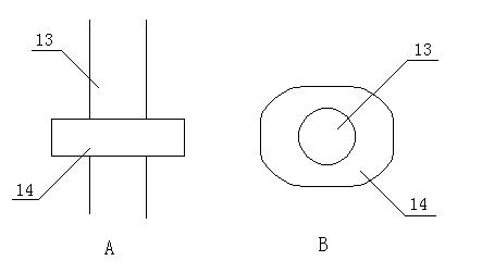
[0036] Such as figure 1 As shown, two partitions are included between adjacent mold cavities 8, and a compartment 9 is formed between the partitions. The compartment 9 includes a partition adjustment device 10 . The partition adjustment device 10 includes two sets of partition adjustment screws 12 and partition adjustment shafts 13 . The partition adjustment screw 12 is located on the top plate 4 and is connected with the partition adjustment shaft 13 . Such as figure 2 As shown, the partition adjustment shaft 13 is equipped with 3-8 axons 14, the horizontal plane of the axons 14 is rectangular, and the four corners are arc-shaped, and the two groups of opposite sides of the axons 14 can support the partition. In use, the distance between the partitions can be changed by turning the partition adjustment screw 12 of the partition adjustment device 10 and then turning the partition adjustment shaft 13 to change the side of the s...
Embodiment 3
[0037] Example 3 cavity mold
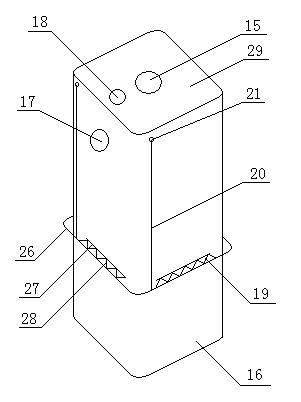
[0038] Such as image 3 As shown, the inner cavity mold is composed of an inner support and an outer wall 16 of the inner cavity mold, and the outer wall 16 of the inner cavity mold wraps the inner cavity mold into a cylinder. The center of the inner cavity mold also includes a central axis 15. Such as Figure 4 As shown, the central axis 15 is connected with the outer wall 16 of the inner cavity mold through a support rod 22 . The central shaft 15 is equipped with a shaft vibrating motor 23 .
PUM
 Abstract
Description
Claims
Application Information
 - R&D
- Intellectual Property
- Life Sciences
- Materials
- Tech Scout
- Unparalleled Data Quality
- Higher Quality Content
- 60% Fewer Hallucinations
Browse by: Latest US Patents, China's latest patents, Technical Efficacy Thesaurus, Application Domain, Technology Topic, Popular Technical Reports.
© 2025 PatSnap. All rights reserved.Legal|Privacy policy|Modern Slavery Act Transparency Statement|Sitemap|About US| Contact US: help@patsnap.com


