Coaxial drive and control structure for coaxial contrarotation rotor helicopter

A technology of rotorcraft and coaxial transmission, which is applied to rotorcraft, motor vehicles, transportation and packaging, etc., can solve problems such as flight accidents, long shafts, and obstacles to the improvement of helicopter lift, so as to reduce production difficulty and cost, Guaranteed strength effect

Active Publication Date: 2012-09-12
李游
View PDF5 Cites 40 Cited by
  • Summary
  • Abstract
  • Description
  • Claims
  • Application Information

AI Technical Summary

Problems solved by technology

Due to the limited number of rotors, the lift of the helicopter is hindered, and the possibility of further enlargement of the coaxial rotor counter-rotating helicopter is also restricted.
At the same time, due to the limited number of rotors, in order to ensure the lift, the arm span of the rotors can only be increased. As a result, the upper rotor and the lower rotor are likely to collide during large-scale maneuvering flight, resulting in flight accidents.
Moreover, due to the long shaft and long rotor, the increase in structural weight caused by the complexity of the control device has also offset the advantages of the coaxial rotor counter-rotating helicopter

Method used


Image

  • Coaxial drive and control structure for coaxial contrarotation rotor helicopter
  • Coaxial drive and control structure for coaxial contrarotation rotor helicopter
  • Coaxial drive and control structure for coaxial contrarotation rotor helicopter

Examples


Embodiment Construction

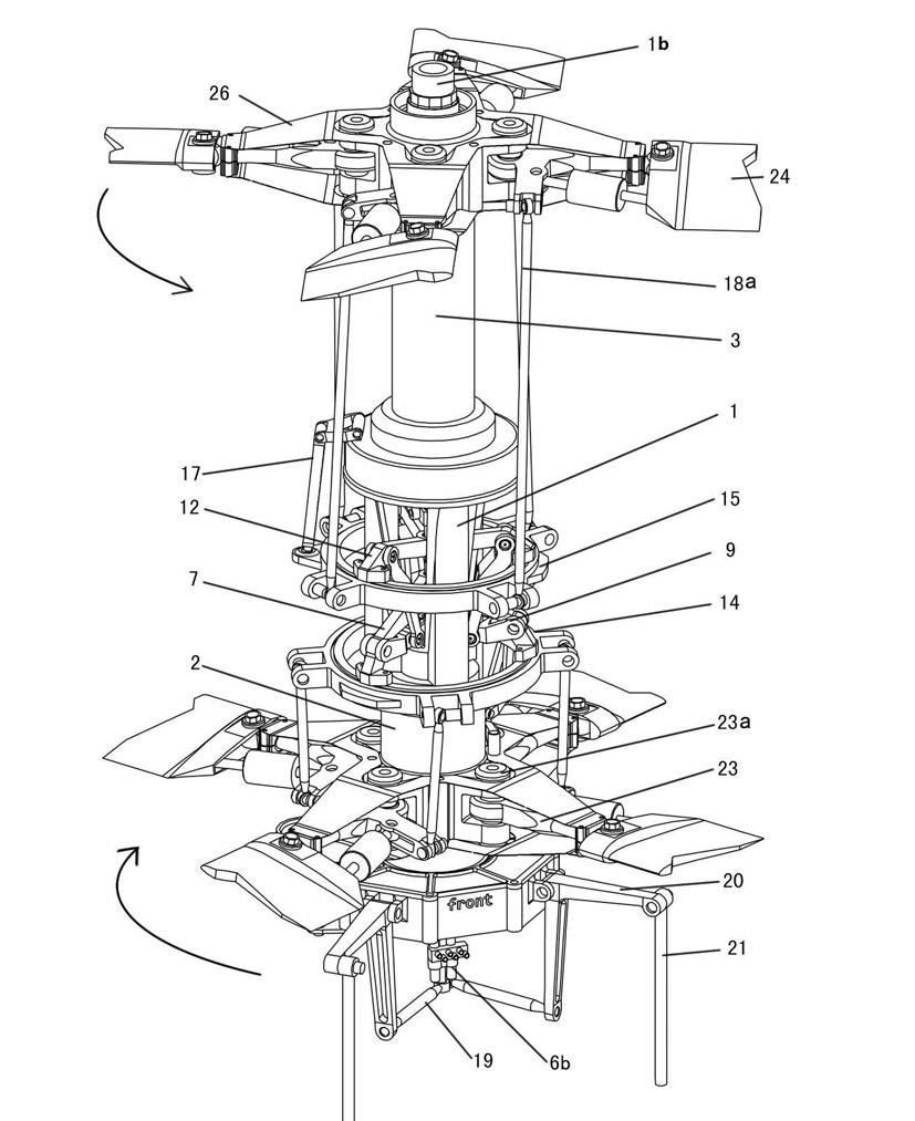
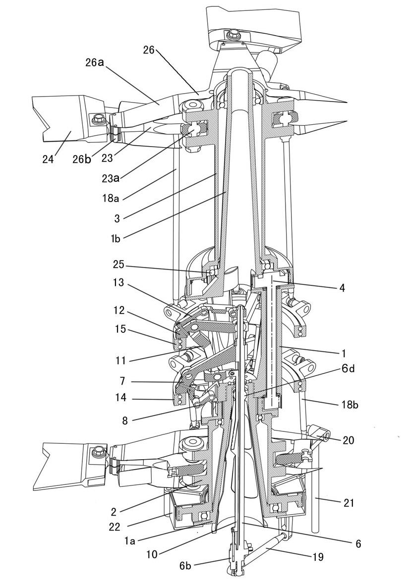
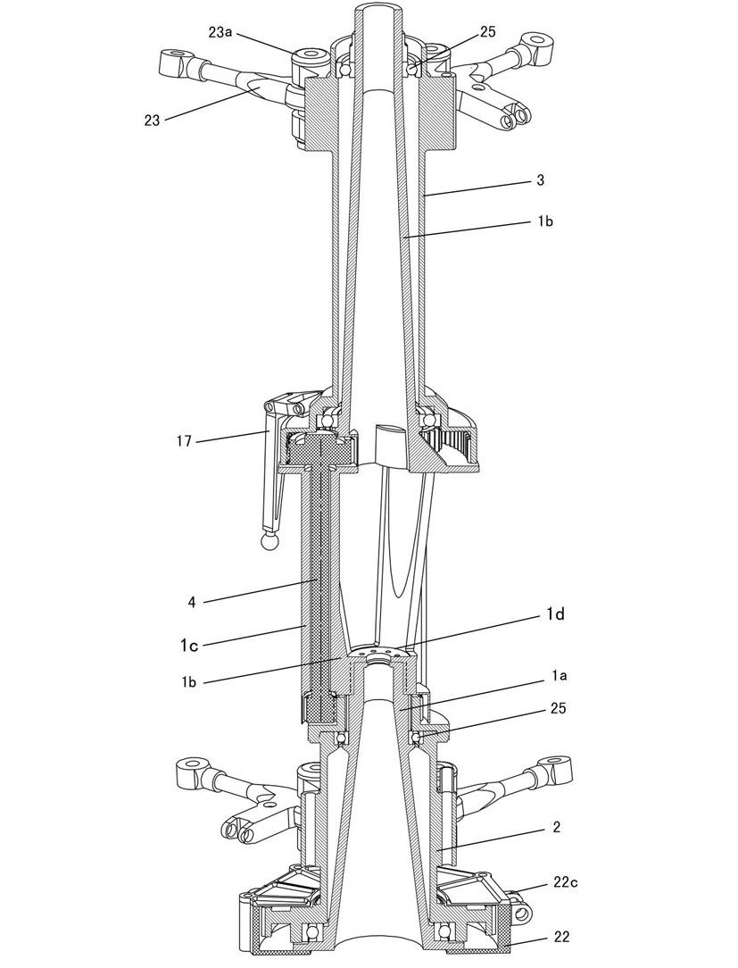
[0034] see Figure 1 to Figure 5 and Figure 8 , a coaxial transmission and control structure of a coaxial counterrotor helicopter, comprising a main shaft, an upper rotor hub 3, a lower rotor hub 2, a gear transmission shaft 4, an upper tilter 15, a lower tilter 14, an upper tilter Bracket 12, lower tilter bracket 7, upper synchronous arm 17, lower synchronous arm 16, upper rotor control lever 18a, lower rotor control lever 18b, rotor control arm 23, main pitch control lever 6, total pitch sliding sleeve 5, etc. The main components. The main shaft is a hollow fixed shaft 1 used to support the rotor hub, the lower end of the fixed shaft 1 is fixedly connected to the housing of the reducer 22, and the fixed connection can be fastened by multiple bolts or fixed by multi-point riveting , or fixed by welding. The housing of the speed reducer 22 is fixedly connected on the fuselage of the helicopter, and its fixing method adopts the usual fixed connection method of the helicopte...


PUM


Abstract

The invention relates to a coaxial drive and control structure for a coaxial contrarotation rotor helicopter. A spindle is a hollow fixed shaft, the fixed shaft is provided with an upper rotor hub and a lower rotor hub, the upper rotor hub and the lower rotor hub are connected by virtue of a gearing shaft, the middle section of the fixed shaft comprises multiple support pillars which are uniformly distributed, an upper inclinator support and a lower inclinator support are arranged in spaces among the support pillars, a total propeller pitch sliding sleeve is arranged inside the lower section of the fixed shaft, a primary variable-pitch control rod is arranged in the total propeller pitch sliding sleeve and is located and hinged by virtue of a ball shaft, the upper part of the primary variable-pitch control rod is connected with the upper inclinator support and the lower inclinator support, and the lower end of the primary variable-pitch control rod is respectively hinged with a variable-pitch rocker arms by virtue of two variable-pitch connecting rods; and an upper inclinator and a lower inclinator are arranged between the upper rotor hub and the lower rotor hub and are hinged with an upper rotor control arm and a lower rotor control arm by virtue of an upper rotor control rod and a lower rotor control rod. By adopting the coaxial drive and control structure for the coaxial contrarotation rotor helicopter disclosed by the invention, the defect that a rotation control assembly penetrates a rotating surface is eliminated, thus the coaxial contrarotation rotor helicopter can be provided with more upper rotors and more lower rotors, lifting power of the helicopter is improved, full differentiating control can be realized, and manufacturing and processing costs of the spindle also can be reduced.

Description

technical field [0001] The invention relates to a transmission and control structure of a helicopter rotor, in particular to a coaxial transmission and control structure of a coaxial counter-rotor helicopter. Background technique [0002] Compared with single-rotor helicopters, coaxial rotor counter-rotating helicopters have multiple advantages such as relatively short rotor span, low power consumption, relatively small fuselage without empennage, and more flexibility. The structure of the helicopter is complex, and the reliability of the flight control is reduced. At present, only the coaxial rotor counter-rotating helicopter designed and manufactured by Russia's Kamov Design Bureau can enter the practical state. Taking the Kamov helicopter as an example, its coaxial structure is an inner and outer shaft structure, the upper rotor hub is fixedly connected to the inner shaft for installing the upper rotor, and the lower rotor hub is fixedly connected to the outer shaft for ...

Claims


Application Information

Patent Timeline
Patent Type & Authority Applications(China)
IPC IPC(8): B64C27/12B64C27/59
Inventor 李游
Owner 李游
Why Eureka
Try Eureka