Check patentability & draft patents in minutes with Patsnap Eureka AI!

Magnetorheological damper with convenience in assembly and disassembly of coil component

A magneto-rheological damper and coil assembly technology, applied in vibration suppression adjustment, non-rotational vibration suppression, etc., can solve problems such as limiting the adjustment range of damping force, easily generating magnetic field saturation, and reducing the effective stroke of the piston, etc., to achieve improved Effects of effective stroke, temperature reduction and service life improvement

Active Publication Date: 2012-09-12
SHIJIAZHUANG TIEDAO UNIV
View PDF5 Cites 29 Cited by
  • Summary
  • Abstract
  • Description
  • Claims
  • Application Information

AI Technical Summary

Problems solved by technology

[0004] (1) The coil is surrounded by magneto-rheological fluid. Since the coil is energized and the heat generated by the damper is concentrated near the coil, it is easy to burn out the coil.
[0005] (2) When the coil is replaced after the coil is burned out, it is necessary to disassemble the seal of the cylinder to replace the coil, which brings inconvenience to the maintenance work
[0006] (3) Since the coil needs to be connected to an external power supply, the guide wire needs to be drilled through the piston rod. If the seal is not good, it is easy to leak
[0007] (4) The structure of the piston is too compact, which is prone to magnetic field saturation, which limits the adjustment range of the damping force
[0008] (5) The axial dimension of the piston is relatively large. When the axial installation dimension of the damper is limited, the effective stroke of the piston will be reduced, especially when a multi-stage piston is used to improve the damping force of the damper. will be more obvious

Method used


Image

  • Magnetorheological damper with convenience in assembly and disassembly of coil component
  • Magnetorheological damper with convenience in assembly and disassembly of coil component
  • Magnetorheological damper with convenience in assembly and disassembly of coil component

Examples


Embodiment Construction

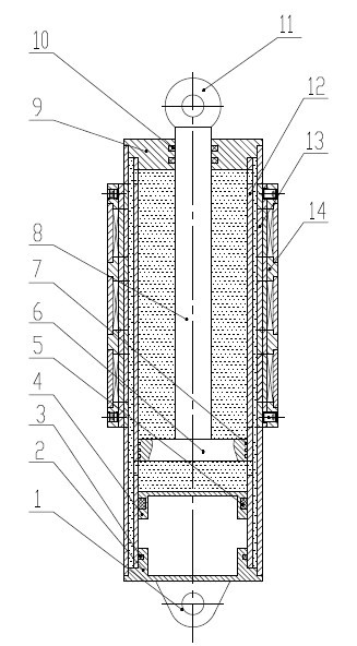
[0031] Such as figure 1 As shown, a magneto-rheological damper with easy assembly and disassembly of the coil assembly includes a damping cylinder, a coil assembly 14, a piston 6, a piston rod 8 and a magneto-rheological fluid, and is characterized in that the coil assembly 14 is fastened by a 141 is fixed on the outside of the damping cylinder, and the damping cylinder is provided with a magneto-rheological fluid flow channel, and the coil assembly 14 can be taken out only by loosening the fastening screw 141 when the coil assembly 14 is disassembled.

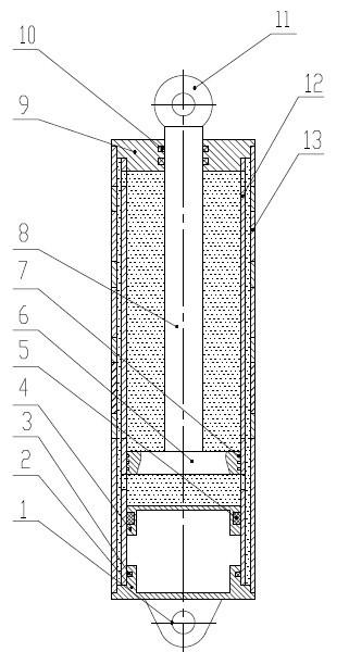
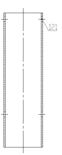
[0032] Such as figure 2 As shown, the damping cylinder includes a cylinder bottom 2, a floating piston 4, an upper cover 9, an inner cylinder 12 and an outer cylinder assembly 13, and the floating piston 4, the upper cover 9 and the inner cylinder 12 are The formed cavity is a magnetorheological fluid cavity. Such as image 3 As shown, the upper and lower ends of the inner cylinder 12 are provided with a plurality of flow ...


PUM


Abstract

The invention discloses a magnetorheological damper with convenience in assembly and disassembly of a coil component, relating to the technical field of magnetorheological dampers. The magnetorheological damper comprises a damping cylinder barrel, the coil component, a piston, a piston rod and a magnetorheological fluid, and is characterized in that the coil component is fixed on the outer side of the damping cylinder barrel, a magnetorheological fluid flow channel is arranged on the damping cylinder barrel, the coil component is not in contact with the magnetorheological fluid, the coil component is simple to assemble and disassemble, and the heat generated by energy consumption of an electromagnetic coil and the magnetorheological damper can be uniformly dissipated through the whole outer-layer cylinder barrel component and the coil component, thus the heat dissipation area is large, the temperature of the electromagnetic coil can be obviously reduced, and the service life of the electromagnetic coil can be prolonged.

Description

technical field [0001] The invention relates to the technical field of magnetorheological fluid dampers, in particular to a magnetorheological damper with convenient assembly and disassembly of coil components. Background technique [0002] The magnetorheological damper is a new type of semi-active damping device. It is developed according to the principle that the rheological characteristics of magnetorheological fluid can be controlled under the action of a magnetic field. It has the advantages of wide adjustment range of damping force, fast response speed, simple structure and easy control. , is an efficient vibration isolation and anti-seismic device, and has been successfully applied in the fields of vehicle system vibration isolation and building structure anti-seismic. [0003] The common magnetorheological damper winds the electromagnetic coil on the piston of the damper, and an annular channel is set on the piston or between the piston and the cylinder. During opera...

Claims


Application Information

Patent Timeline
IPC IPC(8): F16F9/53
Inventor 杨绍普邢海军王兴民
Owner SHIJIAZHUANG TIEDAO UNIV
Features
  • R&D
  • Intellectual Property
  • Life Sciences
  • Materials
  • Tech Scout
  • Unparalleled Data Quality
  • Higher Quality Content
  • 60% Fewer Hallucinations
Learn More