Pipeline corner connector and application method thereof

A technology for corner joints and pipelines, applied in the direction of pipes/pipe joints/pipes, branch pipelines, pipes, etc., can solve the problems of difficult subsequent processing, complex flange structure, large space occupation, etc., and achieve simple machining. , the structure is simple, the effect of occupying a small space

Inactive Publication Date: 2012-09-12
重庆界石仪表有限公司
View PDF10 Cites 6 Cited by
  • Summary
  • Abstract
  • Description
  • Claims
  • Application Information

AI Technical Summary

Problems solved by technology

Existing corner joints are generally connected by threaded elbows or flanged elbows. Since the screwed elbows are randomly tightened, it is difficult to fix the connecting branch or external equipment at the specified position. The equipment is easy to interfere with the wall or other related parts, which makes installation difficult; and the flange elbow is inconvenient to install and takes up a lot of space due to the complex structure and large volume of the flange itself.
[0003] In addition, whether it is a threaded elbow or a flanged elbow, they are all one-piece, especially the elbow part is integrally formed, the manufacturing and subsequent processing are relatively difficult, and the production cost is high.

Method used


Image

  • Pipeline corner connector and application method thereof
  • Pipeline corner connector and application method thereof
  • Pipeline corner connector and application method thereof

Examples


example 1

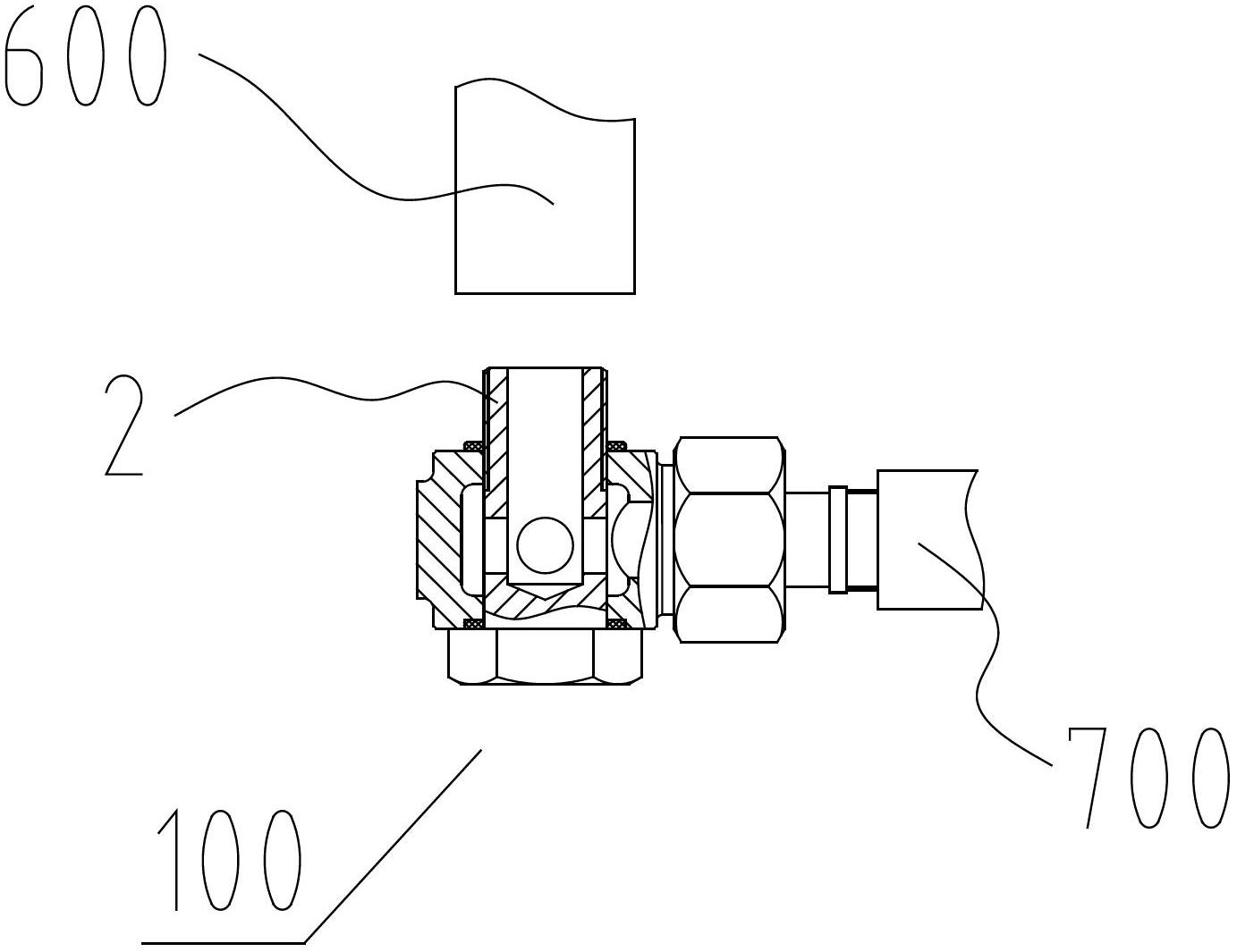
[0037] Example 1: Take the installation of the pipeline corner joints 100 and 200 between the two pipelines, that is, between the main pipe 600 and the branch pipe 700, as an example for illustration.

[0038] Including the following steps,

[0039] a. Fix the main pipe 600 connected with the branch pipe 700 on the wall or at a predetermined position through pipeline fixing nails in advance;

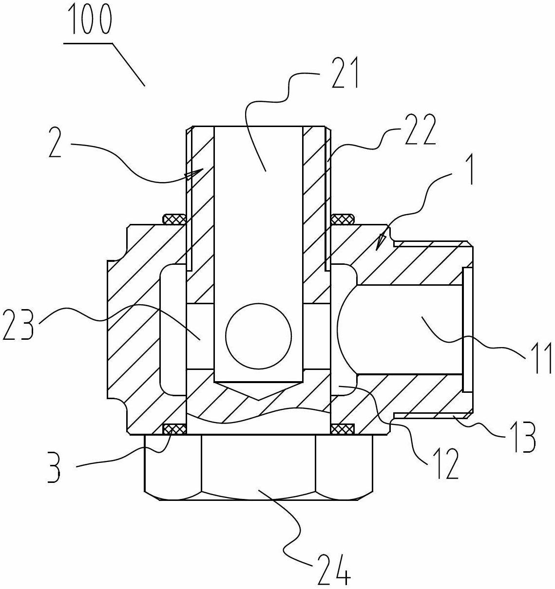
[0040] b. Screw the joint bodies 1, 5 on the pipeline corner joints 100, 200 to the aforementioned branch pipe 700;

[0041] c. Determine the relative installation position of the branch pipe 700 according to the position of the aforementioned main pipe 600;

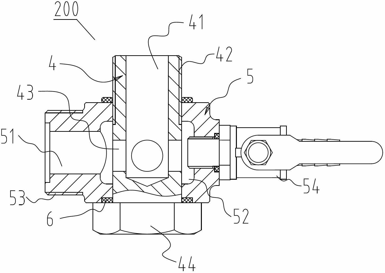
[0042] d. Turn the tool tightening parts 24, 44 of the connectors 2, 4 on the joint body 1, 5 by a wrench or other installation tools, and make the connector body 1, 5 and the branch pipe 700 stationary 2,4 are connected with the main pipe 600 threads.

[0043]Wherein, between step c and step d, or after step d, the position of ...

example 2

[0044] Example 2: The installation of the pipe corner joints 100 and 200 in a pressure regulator will be described. Such as figure 1 , figure 2 , Figure 5 shown.

[0045] a. Two main circuit voltage regulators 400 and 500 are fixedly installed in advance.

[0046] b. The pipeline corner joints 100, 200 are respectively arranged at both ends of a sub-circuit pressure regulator 300, wherein, the connecting thread 13 of the joint body 1 on the pipeline corner joint 100 and the connection thread 13 of the sub-circuit pressure regulator 300 One end is threadedly connected, and the connecting thread 53 of the joint body 5 on the pipeline corner joint 200 is threadedly connected with the other end of the secondary pressure regulator 300 .

[0047] c. After the pipeline corner joints 100, 200 are fixedly connected with the auxiliary road pressure regulator 300 to form a part, the main road pressure regulators are respectively connected to the connecting pieces 2 and 4 on the pip...


PUM


Abstract

The invention discloses a pipeline corner connector and an application method of the pipeline corner connector. The pipeline corner connector comprises a connector body which is provided with a hollow channel along the axial direction, a connecting piece which is arranged on the connector body in a penetrating manner and can relatively rotate; a middle axis of the connecting piece and a middle axis of the connector body are arranged to form an angle; and a communication hole which is communicated with the hollow channel is formed in the connecting piece along the axial direction. The pipeline corner connector is mounted by the following steps of: a. fixing a main pipe position communicated with a branch pipe in advance; b. fixedly connecting the connector body with the branch pipe; c. determining a relative position of the branch pipe according to the position of a main pipe; and d. rotating the connecting piece on the connector body and connecting the connecting piece with the main pipe under the condition that the connector body and the branch pipe are immobile. The pipeline corner connector can be mounted on a needed effective position to be positioned and has the advantage of simple structure, convenience for installation and rapidness; an interference position does not need to be preserved on a mounting space and an occupied space is small; and meanwhile, the pipeline corner connector has the advantages of simplicity in early-stage machining, low production cost and suitableness for popularization.

Description

technical field [0001] The invention relates to a pipeline corner joint and its use method, in particular to a pipeline corner joint for gas pipes, more precisely, a gas pipeline corner joint that can be positioned at any position. Background technique [0002] During the laying of gas pipelines, it is often necessary to set up a corner joint at the corner of the wall to continue the pipeline, or some main pipelines need to connect external equipment or branch pipes through the corner joint. Existing corner joints are generally connected by threaded elbows or flanged elbows. Since the screwed elbows are randomly tightened, it is difficult to fix the connecting branch or external equipment at the specified position. The equipment is easy to interfere with the wall or other related parts, which makes installation difficult; and the flange elbow is inconvenient to install and takes up a lot of space due to the complex structure and large volume of the flange itself. [0003] I...

Claims


Application Information

Patent Timeline
Patent Type & Authority Applications(China)
IPC IPC(8): F16L27/00F16L41/00
CPCF16L41/005
Inventor 廖礼庆
Owner 重庆界石仪表有限公司
Why Eureka
Try Eureka