Method for producing glass film

A manufacturing method and glass film technology, applied in glass manufacturing equipment, glass molding, glass molding, etc., can solve the problems of thickness change, variable size, uneven thickness, etc., and achieve the effect of stable flow

Inactive Publication Date: 2014-11-05
NIPPON ELECTRIC GLASS CO LTD
View PDF3 Cites 1 Cited by
  • Summary
  • Abstract
  • Description
  • Claims
  • Application Information

AI Technical Summary

Problems solved by technology

Therefore, when the molten glass is supplied from the melting furnace to the forming device and the glass film is formed by the down-draw method, the thickness may vary or the thickness unevenness may easily increase due to fluctuations in the flow rate of the molten glass flowing through the forming device. , it is difficult to increase productivity

Method used


Image

  • Method for producing glass film
  • Method for producing glass film
  • Method for producing glass film

Examples


Embodiment Construction

[0026] Hereinafter, embodiments of the present invention will be described in detail with reference to the drawings.

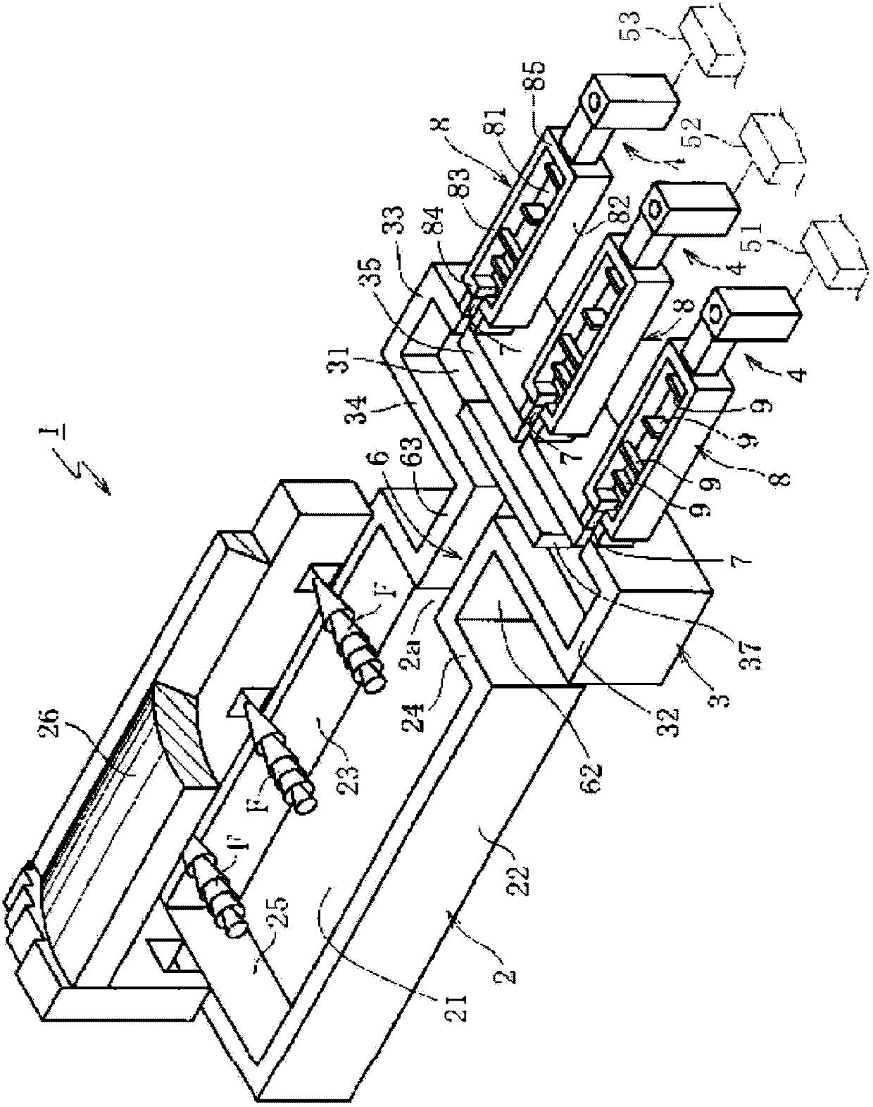
[0027] First, refer to figure 1 The whole structure of the molten-glass supply facility which concerns on embodiment of this invention is demonstrated. This molten glass supply facility 1 has a substantially rectangular melting furnace 2 constituting a supply source of molten glass, a distribution chamber (distribution portion) 3 communicating with the outflow port 2 a of the melting furnace 2 , and a downstream side end portion of the distribution chamber 3 . The plurality of branch flow paths 4 communicated at approximately equal intervals, and the downstream end portions of the branch flow paths 4 communicate with the plurality of molding devices 51 to 53 , respectively. It should be noted that there are three paths to the molding devices 51 to 53 through the branch channel 4 in the figure, but there may be two paths, or four or more paths.

[0028] The m...


PUM

PropertyMeasurementUnit
thicknessaaaaaaaaaa
thicknessaaaaaaaaaa
thicknessaaaaaaaaaa

Abstract

Provided is a method, including: a melting step of melting glass in a melting furnace 2; a distribution step of supplying the molten glass in the melting furnace 2 to a plurality of branched channels 4; and a forming step of supplying the molten glass flowing out from each of the plurality of branched channels 4 to one of a plurality of forming apparatuses 51 to 53 communicating with the plurality of branched channels 4, respectively, and forming the molten glass into a plate-shaped glass by a down-draw method, in which one or more of the plurality of forming apparatuses 51 to 53 are used to form a glass film having a thickness of 1 to 200 μm.

Description

technical field [0001] The present invention relates to a method for producing glass films used in flat panel displays, solar cells, organic EL lighting, and the like. Background technique [0002] From the viewpoint of saving space, flat panel displays such as liquid crystal displays, plasma displays, organic EL displays, and field emission displays have been widely used instead of CRTs in recent years. These flat panel displays are required to be further thinned. In particular, organic EL displays are required to be easily transported by folding or winding, and to be able to be mounted not only on a flat surface but also on a curved surface. [0003] In addition, the demand for installation on curved surfaces is not limited to displays, and solar cells or organic EL lighting are expected to be formed on the surfaces of objects with curved surfaces such as vehicle body surfaces, roofs, columns, and outer walls of buildings, for example. Therefore, for various glass substra...

Claims


Application Information

Patent Timeline
Patent Type & Authority Patents(China)
IPC IPC(8): C03B17/06C03B7/02
CPCC03B17/06C03B17/064Y02P40/57C03B5/08C03B17/062C03B17/068C03B35/06
Inventor 笘本雅博织田英孝石桥真一高谷辰弥藤原克利
Owner NIPPON ELECTRIC GLASS CO LTD
Why Eureka
Try Eureka