

Efficient gas-liquid separator
A gas-liquid separator and pre-separator technology, applied in separation methods, dispersed particle separation, chemical instruments and methods, etc., to achieve the effect of improving the passing capacity, reducing the impact, and reducing the overall height
- Summary
- Abstract
- Description
- Claims
- Application Information
AI Technical Summary
Problems solved by technology
Method used
Image

Examples
Embodiment Construction
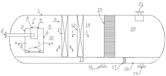
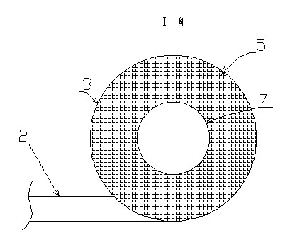
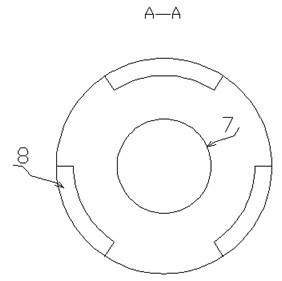
[0039] As shown in the figure, the high-efficiency gas-liquid separator includes a shell 1, a feed inlet 2, a pre-separator 3, an air guide tube 4, a cover plate 5, a swirl tube 6, a circular platform isolation plate 7, a liquid guide tank 8, a gas phase Zone 9, pre-separation zone 10, first layer of vane packing 11, second layer of vane packing 12, liquid phase zone 13, main separation zone 14, wire mesh demister 15, sewage outlet 16, isolation plate 17, collector Liquid chamber 18, liquid outlet 19, dry gas area 20, gas outlet 21;
[0040]The front end of the housing 1 is provided with a feed port 2, the upper part of the rear section of the housing 1 is provided with a gas outlet 21, the lower part of the housing 1 is provided with a sewage outlet 16, and the lower part of the rear end is provided with a liquid outlet 19, and the upper part of the housing 1 is a gas phase area 9. The lower part of the housing 1 is a liquid phase area 13, and the gas phase area 9 in the hous...
PUM
| Property | Measurement | Unit |
|---|---|---|
| Height | aaaaa | aaaaa |
| Thickness | aaaaa | aaaaa |
Abstract
Description
Claims
Application Information