Take-up tension control mechanism for wire drawing machine

A technology of tension control mechanism and wire drawing machine, which is applied in the field of tension control mechanism for take-up, can solve the problems of easy failure, complex operation principle, complex mechanism, etc., and achieves the effects of being less prone to failure, simple in structure, and simple in control and operation.

Inactive Publication Date: 2012-09-19
浙江奥通机械科技有限公司
View PDF7 Cites 3 Cited by
  • Summary
  • Abstract
  • Description
  • Claims
  • Application Information

AI Technical Summary

Problems solved by technology

When taking up the wire, it is necessary to adjust the tension of the wire to prevent the wire from being over-feeding or being broken. The e

Method used


Image

  • Take-up tension control mechanism for wire drawing machine
  • Take-up tension control mechanism for wire drawing machine

Examples


Embodiment Construction

[0010] The present invention will be described in further detail below in conjunction with the accompanying drawings and specific embodiments.

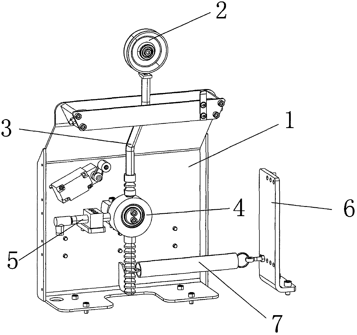
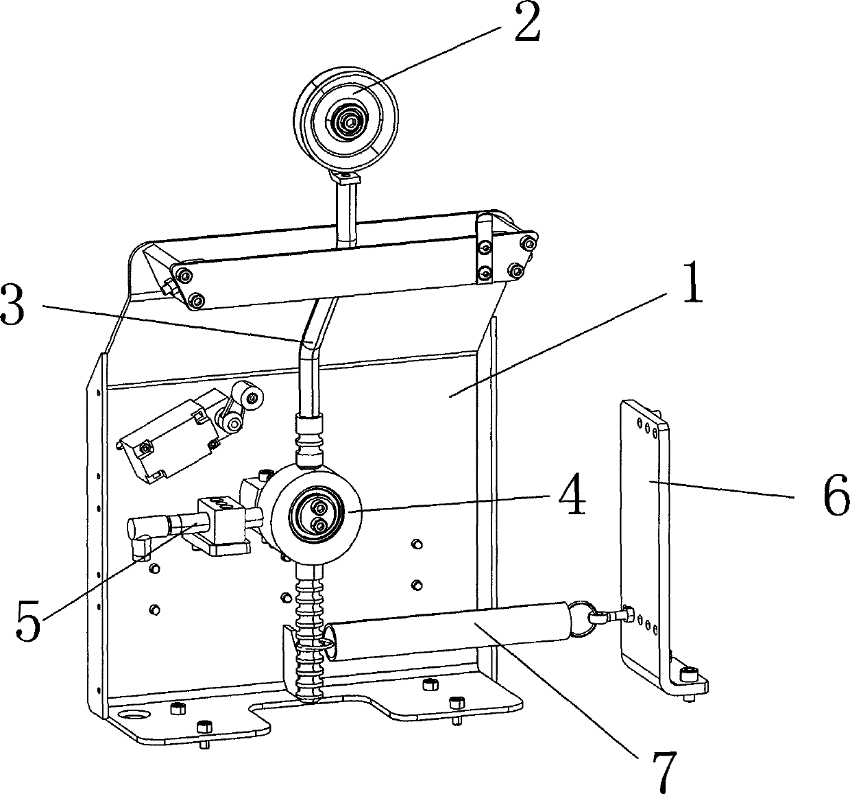
[0011] refer to figure 1 , a take-up tension control mechanism for a wire drawing machine, including a frame body 1, a wire passing wheel 2, and a swing rod 3 located on the back of the frame body 1, and the wire passing wheel 2 is arranged on the pendulum On the upper end of the rod 3, the swing rod 3 is provided with an eccentric wheel 4, and the back side of the frame body 1 is provided with a rotating shaft, and the described eccentric wheel 4 is eccentrically mounted on the rotating shaft.

[0012] A distance sensor 5 is also provided on the back of the frame, and the distance sensor 5 is located on one side of the eccentric wheel 4 .

[0013] In this embodiment, the front of the swing rod 3 is also provided with a fixed plate 6, and also includes a tension spring 7, one end of the tension spring 7 is hooked on the fixed plate 6...


PUM


Abstract

The invention discloses a take-up tension control mechanism for a wire drawing machine. The take-up tension control mechanism comprises a support, a wire roller and an oscillating bar positioned on the back of the support, wherein the wire roller is arranged at the upper end of the oscillating bar; an eccentric wheel is arranged on the oscillating bar; a rotating shaft is arranged on the back of the support; the eccentric wheel is inserted in the rotating shaft in an eccentric way; and a distance sensor is arranged on the back of the support and is positioned on one side of the eccentric wheel. The take-up tension control mechanism for the wire drawing machine is simple in structure and easy to control and operate, and hardly has faults.

Description

(1) Technical field [0001] The invention relates to a take-up tension control mechanism of a wire drawing machine. (2) Background technology [0002] With the shortage of energy in the world, the use of solar power to generate electricity has attracted more and more attention from all countries, so the photovoltaic industry has also been greatly developed. The utilization of solar energy mainly converts solar energy into electrical energy according to the photovoltaic characteristics of polycrystalline silicon or monocrystalline silicon. In this conversion process, polycrystalline silicon or monocrystalline silicon is generally in the form of flakes. Due to technical limitations, when producing polycrystalline silicon or monocrystalline silicon, only polycrystalline silicon or monocrystalline silicon rods can be produced. To obtain polycrystalline silicon or monocrystalline silicon wafers , the general method is to use cutting steel wire to cut silicon rods into silicon waf...

Claims


Application Information

Patent Timeline
IPC IPC(8): B21C47/04B21C1/02
Inventor 罗文君胡东辉谢磊马文霍颖锋
Owner 浙江奥通机械科技有限公司
Why Eureka
Try Eureka