
Tool rest

A tool holder and cutter head technology, applied in the direction of tool holders, etc., can solve the problems of high matching accuracy, inability to apply synchronous processing, and complicated tool holder assembly structure, so as to improve processing efficiency, save replacement time, and facilitate assembly and disassembly Effect

Active Publication Date: 2012-09-19
ZHEJIANG MOTORBACS TECH
View PDF7 Cites 26 Cited by
  • Summary
  • Abstract
  • Description
  • Claims
  • Application Information

AI Technical Summary

Problems solved by technology

[0004] However, the tool holder assembly structure of the above-mentioned patent is relatively complicated, and the rotary motion of the tool holder needs to be realized through the cooperation of various couplers. The rotation of the turret part cannot realize the simultaneous work of multiple cutter heads installed on the tool holder, and it cannot be applied to the requirements of multi-station synchronous processing in pipe end processing equipment. Therefore, further improvement is still needed

Method used


Image

  • Tool rest
  • Tool rest
  • Tool rest

Examples


Embodiment Construction

[0023] The present invention will be further described in detail below in conjunction with the accompanying drawings and embodiments.

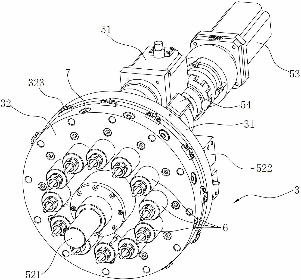
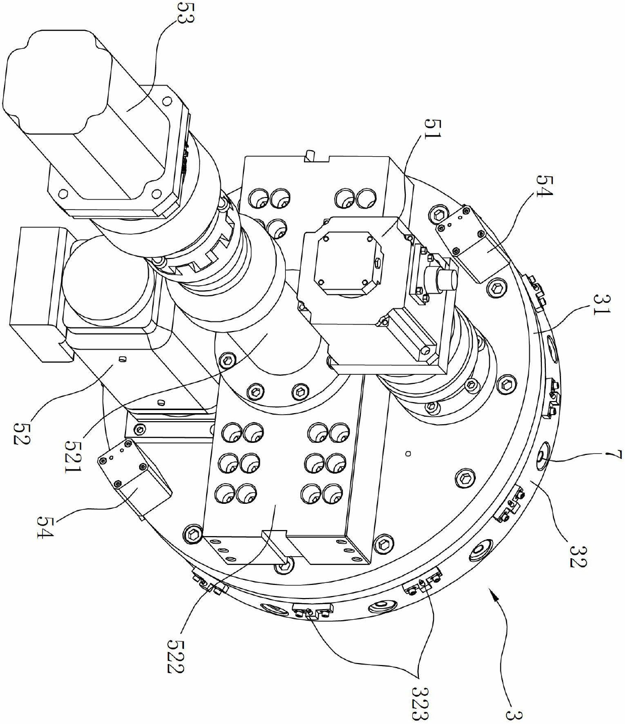
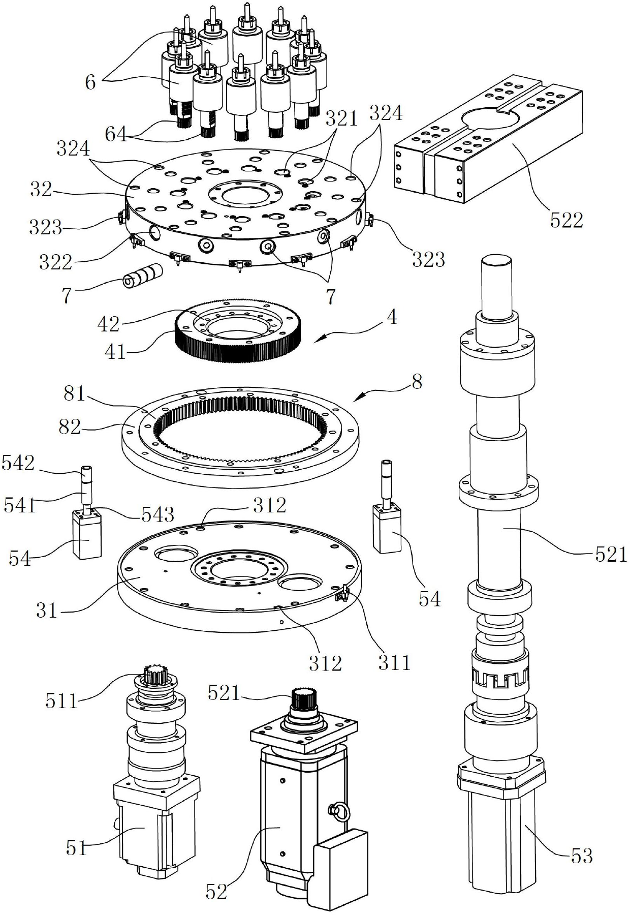
[0024] Such as Figure 1 to Figure 7 As shown, this embodiment is a tool rest 3 installed on the machine base of the pipe end processing equipment. The tool rest 3 adopts a turret structure, which includes a vertically arranged fixing plate 31 and is rotatably connected to the The cutter head 32 on the fixed plate 31 is equipped with a plurality of cutters 6 for processing the end face of the pipe fittings along the circumference of the cutter head 32, and the tool holder 3 is also provided with a drive tool holder 3 along the direction approaching or away from the workbench. The main driving device for linear motion, the main driving device includes a third motor 53, a screw shaft 521 and a push plate 522, the tool rest 3 is provided with an axial hole for the screw shaft 521 to pass through in the axial direction, and the push plate 522 is ...


PUM


Abstract

The invention relates to a tool rest, which is arranged on a base, and is characterized in that the tool rest comprises a fixed plate and a cutter disc capable of being rotatably connected to the fixed plate; and a plurality of cutters are arranged on the cutter disc along the circumference. Compared with the prior art, the tool rest has the advantages that the tool rest adopts a turret-style structure, the cutters are respectively arranged on the same side face of the cutter disc, and the assembly and disassembly are more convenient; secondly, the cutter disc is of a rotatable structure, a plurality of cutters with different functions can be arranged, the cutters can be replaced by rotating the cutter disc, the trouble that the cutter needs to be replaced when each procedure is processed is avoided, the time for replacing the cutter is saved, and the processing efficiency is improved; and the rotation of the cutter disc relative to the fixed plate is realized through a turntable bearing.

Description

technical field [0001] The invention relates to a tool holder, in particular to a tool holder for pipe end processing equipment. Background technique [0002] In large lathes, machine tools or automated CNC processing equipment, in order to improve processing efficiency and realize simultaneous processing and mass production of multiple workpieces, such equipment is usually equipped with a tool holder that can install multiple tools, and each tool is processed according to the order It is pre-adjusted. After cutting once, the tool holder returns and rotates, and then cuts with another knife, so it can complete the processing of more complex surfaces in one clamping of the workpiece. [0003] In the prior art, the Chinese utility model "Turret Tool Holder" with the patent number ZL201120011102.5 provides a turret tool holder. , so that the specified tool is indexed and called; the curved coupler is converted into a coupling mode and a decoupling mode. In the coupling mode, t...

Claims


Application Information

Patent Timeline
IPC IPC(8): B23B29/32
Inventor 陆志伟陈军
Owner ZHEJIANG MOTORBACS TECH
Features
  • Generate Ideas
  • Intellectual Property
  • Life Sciences
  • Materials
  • Tech Scout
  • Unparalleled Data Quality
  • Higher Quality Content
  • 60% Fewer Hallucinations
Learn More