Simple positioning and drilling clamp

A drilling jig, a simple technology, applied in the direction of the drilling mold used for workpieces, etc., can solve the problems of inconvenient scribing and positioning one by one, insufficient drilling positioning accuracy, and high manual labor intensity, so as to achieve low manual labor intensity, Simple structure and high work efficiency

Inactive Publication Date: 2012-09-19
苏州金牛精密机械有限公司
View PDF7 Cites 5 Cited by
  • Summary
  • Abstract
  • Description
  • Claims
  • Application Information

AI Technical Summary

Problems solved by technology

[0002] In the process of mechanical processing, drilling is one of the main processing procedures of parts processing. Before drilling, the position of the drilling hole must be determined first. Line positioning is very inconvenient, especially when parts are mass-produced, not only the labor intensity is high, the work efficiency is low, but also the drilling positioning accuracy is not enough, and the yield rate of parts is low

Method used


Image

  • Simple positioning and drilling clamp
  • Simple positioning and drilling clamp

Examples


Embodiment Construction

[0015] The present invention will be specifically introduced below in conjunction with the accompanying drawings and specific embodiments.

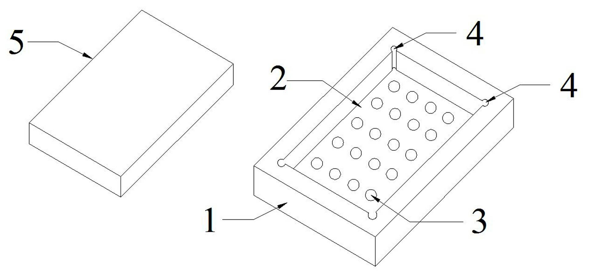
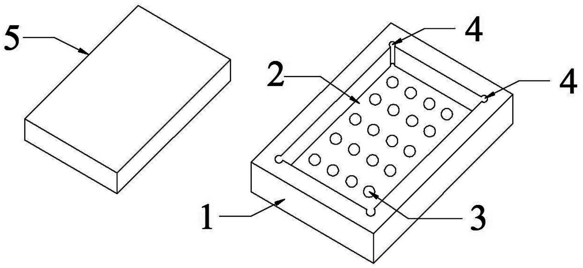
[0016] refer to figure 1 , the simple positioning drilling jig of the present invention includes: a mold base 1 with a horizontal platform, a cavity 2 for clamping a workpiece 5 to be drilled, formed in the cavity 2, and used to guide the drilling tool to be drilled. The workpiece 5 is drilled with a pilot hole 3, and the axial direction of the pilot hole 3 is perpendicular to the plane where the mold base 1 is located. The workpiece 5 to be drilled is placed in the cavity 2 on one side of the mold base 1, and the drilling tool is drilled from the other side of the mold base 1 through the guide hole 3 to the workpiece 5 to be drilled.

[0017] As a preferred solution, the mold cavity 2 is formed by the inward depression of the mold base 1 . In order to make the workpiece 5 to be drilled stably placed in the cavity 2, the bottom su...


PUM


Abstract

The invention discloses a simple positioning and drilling clamp which is characterized by comprising a die holder with a horizontal table top, a die cavity for clamping a work piece to be drilled, a guide hole formed in the die cavity and used for guiding a drilling tool to drill the work piece to be drilled, and a preformed groove recessed from the side wall of the die cavity towards the direction away from the center of the die cavity and used for conveniently taking the work piece to be drilled, wherein the axial direction of the guide hole is perpendicular to the plane where the die holder is positioned. The simple positioning and drilling clamp has the benefits that the drilling clamp has a simple structure and is convenient for fabrication and use, the labor intensity is reduced and the work efficiency is increased, the drilling positioned effect is accurate, the quality of products is improved, and the yield is increased.

Description

technical field [0001] The invention relates to a clamp, in particular to a simple clamp for positioning drilled holes. Background technique [0002] In the process of mechanical processing, drilling is one of the main processing procedures of parts processing. Before drilling, the position of the drilling hole must be determined first. Line positioning is very inconvenient, especially when the parts are mass-produced, not only the labor intensity is high, the work efficiency is low, but also the positioning accuracy of the drilling is not enough, and the yield rate of the parts is low. Contents of the invention [0003] In order to solve the deficiencies of the prior art, the object of the present invention is to provide a drilling jig with a simple structure for accurately positioning the workpiece to be drilled. [0004] In order to achieve the above object, the present invention adopts the following technical solutions: [0005] The simple positioning drilli...

Claims


Application Information

Patent Timeline
Patent Type & Authority Applications(China)
IPC IPC(8): B23B47/28
Inventor 周建荣
Owner 苏州金牛精密机械有限公司
Why Eureka
Try Eureka