Device capable of obtaining water from air

An air and air collector technology, applied in water supply installations, drinking water installations, buildings, etc., can solve the problems of energy consumption, poor reliability and low energy efficiency, and achieve the effect of reducing energy consumption and improving efficiency

Inactive Publication Date: 2012-09-19
SHANGHAI JIAO TONG UNIV
14 Cites 30 Cited by

AI-Extracted Technical Summary

Problems solved by technology

However, the circulation loop in this system is not optimized, and the use of electric heaters to provide heat for the regeneration of the runners requires more energy consumption, and the power also needs to be provided externally.
The Chinese patent application number is 200820025836.7. On the basis of the Chinese patent application number 200820025835.2, the air water intake device and diesel generator are combined to form a shelter, which realizes the self-sufficiency...

Method used

In the present embodiment, after regenerated air exchanges moisture content by dehumidification runner 14 and ambient air, its moisture content is higher than the moisture content of ambient air many times, makes in desert etc. air moisture content is very little It can also work normally in the environment, and the water intake efficiency has been greatly improved. At the same time, the solar air heat collector is used as the heat source for the regeneration of the runner, which reduces the system consumption. Moreover, since the solar photovoltaic cell is used as the powe...

Abstract

The invention discloses a device capable of obtaining water from the air. The device comprises a solar air heat collector, a solar photovoltaic power generation unit, a compression refrigeration unit and a reel dehumidification unit, wherein the solar air heat collector is used as a heat resource for the reel dehumidification unit; the solar photovoltaic power generation unit provides a required power supply to the reel dehumidification unit and the compression refrigeration unit; the compression refrigeration unit is used for compressing and refrigerating; and the reel dehumidification unit is used for eliminating moisture. The device capable of obtaining water from the air utilizes the solar energy as the energy for obtaining water from the air, so that fossil fuel does not need to be carried in the process of obtaining the water from the air, and the energy consumption for obtaining the water from the air is reduced. Meanwhile, compared with a refrigeration and moisture condensation method, the device can normally obtain water when the air humidity is relatively low, water can be continuously fetched, and the water fetching efficiency is improved.

Application Domain

Technology Topic

Fossil fuelMoisture condensation +8

Image

  • Device capable of obtaining water from air
  • Device capable of obtaining water from air

Examples

  • Experimental program(1)

Example Embodiment

[0023] The embodiments of the present invention will be described in detail below with reference to the drawings.
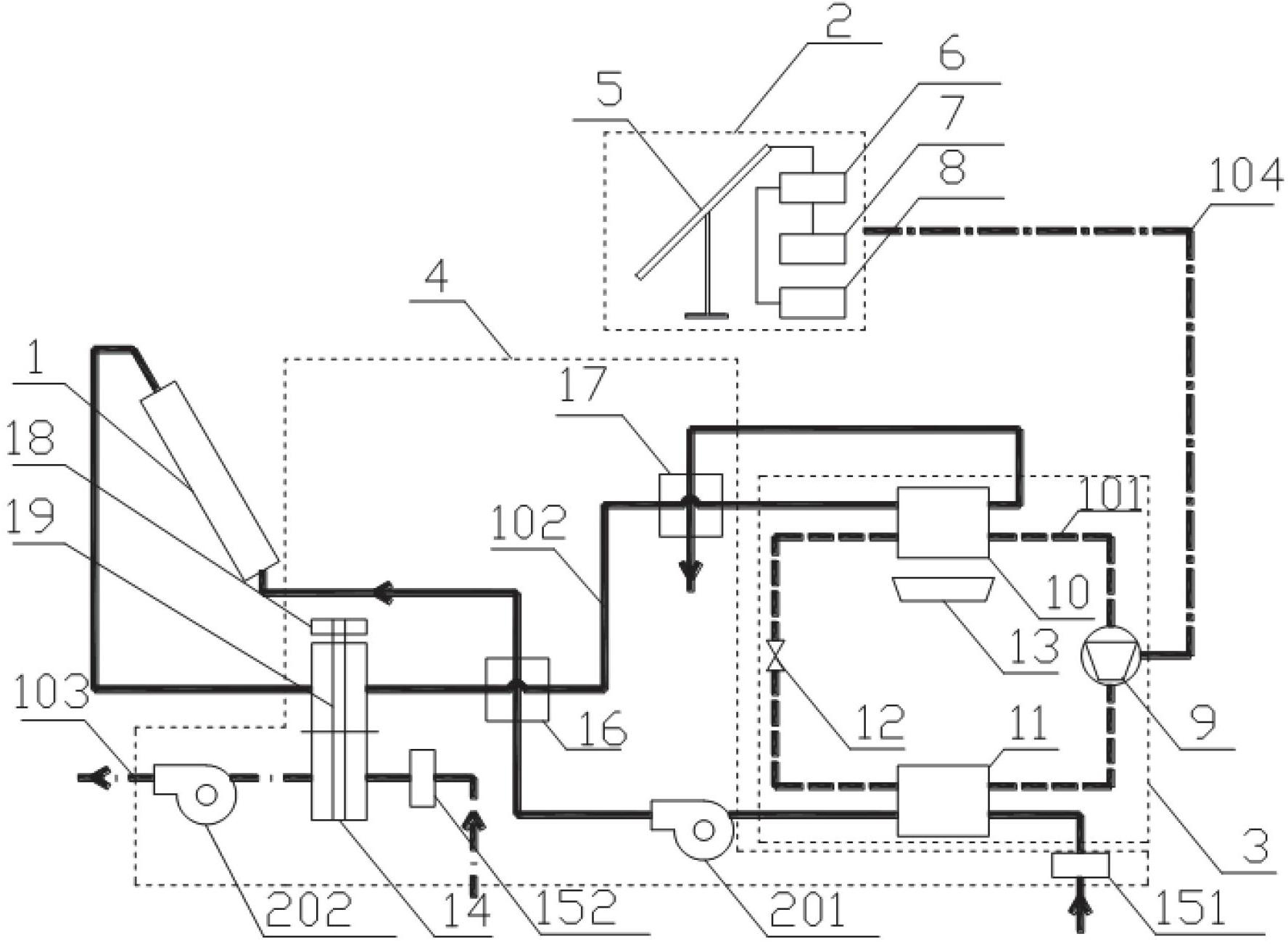
[0024] Such as figure 1 As shown, a device for taking water from the air includes a solar air collector 1, a solar photovoltaic power generation unit 2, a compression refrigeration unit 3, and a rotary dehumidification unit 4, wherein the solar air collector 1 is connected to the The wheel dehumidification unit 4 is connected to the compression refrigeration unit 3, the compression refrigeration unit 3 is also connected to the solar photovoltaic power generation unit 2, and the solar air collector 1 is used as The heat source of the runner dehumidification unit 4, the solar photovoltaic power generation unit 2 provides the power required by the runner dehumidification unit 4 and the compression refrigeration unit 3 through electrical connections, and the compression refrigeration unit 3 is used for compression refrigeration, so The rotary dehumidification unit 4 is used for dehumidification, and the compression refrigeration unit 3 and the rotary dehumidification unit 4 are connected by a wind pipe. In this embodiment, the solar air heat collector 1 is a flat solar air heat collector or a vacuum tube solar air heat collector. The solar photovoltaic power generation unit 2 includes a solar panel 5, a solar power controller 6 and a battery 7 and an inverter 8 to provide DC or AC output. The solar panel is connected to the input terminal of the solar power controller, and the solar power controller has two Each output terminal is connected to the battery and the inverter respectively. The compression refrigeration unit 3 includes: a compressor 9, an evaporator 10, a condenser 11, a throttle valve 12, and a water collector 13. The compressor 9, evaporator 10, condenser 11, and throttle valve 12 are connected in sequence to form a refrigeration unit. Loop 101. Wherein, the refrigerant inlet and the refrigerant outlet of the condenser 11 are respectively connected to the outlet of the compressor 9 and the inlet of the throttle valve 12, and the refrigerant inlet and the refrigerant outlet of the evaporator 10 are respectively connected At the outlet of the throttle valve 12 and the inlet of the compressor 9, the water collector 13 is placed directly below the evaporator 10, and the power terminal of the compressor 9 is connected to the solar photovoltaic power generation unit 2 through the circuit 104. Connected. The compressor 9 may be a DC compressor or an AC compressor. The wheel dehumidification unit 4 includes: a dehumidification wheel 14, a first air filter 151, a second air filter 152, a first heat exchanger 16, a second heat exchanger 17, a wheel drive motor 18, a connecting mechanism 19, The first airflow induced fan 201 and the second airflow induced fan 202, wherein: the first airflow filter 151 and the first air inlet of the first heat exchanger 16 are respectively connected to the compression refrigeration unit 3 The air inlet and air outlet of the condenser 11, the first air outlet of the first heat exchanger 16 is connected to the inlet of the solar air collector 1, and the two ends of the regeneration zone of the dehumidification rotor 14 are respectively connected to The outlet of the solar air heat collector 1 and the second air inlet of the first heat exchanger 16, the second air outlet of the first heat exchanger 16 and the second air outlet of the second heat exchanger 17 The air inlet is connected, the second air outlet of the second heat exchanger 17 is connected with the air inlet of the evaporator 10 of the compression refrigeration unit 3, and the first air inlet of the second heat exchanger 17 is connected to the evaporator The air outlet of the dehumidifier 10 is connected, the two ends of the moisture absorption zone of the dehumidification wheel 14 are respectively connected to the second air draft fan 202 and the second air filter 152, and the dehumidification wheel 14 is connected through the connection The mechanism 19 is connected to the rotor drive motor 18, and the power terminals of the first airflow induced draft fan 201, the second airflow induced fan 202, and the rotor drive motor 18 are connected to the solar photovoltaic power generation unit 2 through a circuit 104, respectively. Connected. The first heat exchanger 16 and the second heat exchanger 17 are cross-flow heat exchangers that exchange heat between air and air. The dehumidification wheel 14 is a porous wheel made of paper or ceramics, and the direction of the holes is the axial direction. The desiccant rotor 14 is provided with a solid desiccant, and the components of the solid desiccant are silica gel, lithium chloride, molecular sieve and composite desiccant. The material of the solar cell panel 5 is monocrystalline silicon or polycrystalline silicon or an amorphous silicon film. The battery 7 is a lead-acid battery.
[0025] The working principle of the device for taking water from the air in this embodiment is as follows: after the moisture absorption treatment airflow passes through the second airflow filter 152, it enters the moisture absorption treatment zone of the dehumidification runner 14, and the water vapor in the moisture absorption treatment airflow is absorbed into the moisture absorbent. The regeneration water airflow is filtered by the first airflow filter 151, enters the condenser 11, uses condensation heat for preheating, and then enters the first air inlet of the first heat exchanger 16 for preheating, and then passes through the solar air collector. Heater 1, raises the temperature of the regeneration water extraction air to more than 40°C higher than the ambient temperature, and then passes through the dehumidification rotor 14 to contact the moisture absorbent in the dehumidification rotor 14, increasing the moisture in the regeneration water extraction air stream, so that The moisture content of the regenerated water increases, forming a high temperature and high humidity air stream. After the high-temperature and high-humidity air flow leaves the dehumidification rotor 14, it first passes through the first heat exchanger 16 to exchange heat with the regenerated water flow preheated by condensation heat for cooling, and then enters the second heat exchanger 17 The air from the evaporator 10 is cooled by heat exchange, so that the temperature of the regeneration water extraction air drops to close to the dew point temperature, and then the regeneration water extraction air is sent to the evaporator 10 to cool below the dew point temperature, and the moisture in the regeneration water extraction air is precipitated. The water collector 13 is used to collect the separated water. The air with a very low temperature after the water is taken is sent to the second heat exchanger 17 to pre-cool the air that has not taken water to recover this part of the cold. Among them, the components through which the moisture absorption treatment airflow and the regeneration water extraction airflow pass are connected by air ducts. The solar photovoltaic power generation unit 2 uses the solar panel 5 to convert solar energy into electric energy. The battery 7 can store electric energy. The solar power controller 6 can control the charging and discharging of the battery 7 to protect the battery 7, and the inverter 8 can convert the solar panel 5 The generated direct current is converted to alternating current. Whether the inverter 8 is connected to the circuit 104 depends on the power supply form of the compression refrigeration device, the fan and the dehumidification rotor motor. If it is a DC power supply, it is not connected, and if it is an AC power supply, it is connected.
[0026] In this embodiment, after the regenerated air exchanges moisture content with the ambient air through the dehumidification rotor 14, its moisture content is many times higher than that of the ambient air, so that it can also be used in deserts and other environments with low air humidity. It can work normally, and the water extraction efficiency has been greatly improved. At the same time, the use of solar air collectors as the heat source for runner regeneration reduces system consumption. Moreover, because solar photovoltaic cells are used as the power source of the compression refrigeration device, the fan, and the dehumidification rotor motor, no other power generation devices and access to the grid are required, which reduces the energy consumption of the entire system. There is no need to carry fuel, so it is suitable for field work. At the same time, because the first heat exchanger and the second heat exchanger are used to effectively recover part of the heat and cold, the system is more efficient. The rotating wheel keeps rotating to ensure that the system can continuously draw water when the sun is on.
[0027] The preferred embodiments of the present invention are described in detail above. It should be understood that those of ordinary skill in the art can make many modifications and changes according to the concept of the present invention without creative work. Therefore, any technical solution that can be obtained by a person skilled in the art through logical analysis, reasoning or limited experiments based on the concept of the present invention on the basis of the prior art should fall within the protection scope determined by the claims.

PUM

no PUM

Description & Claims & Application Information

We can also present the details of the Description, Claims and Application information to help users get a comprehensive understanding of the technical details of the patent, such as background art, summary of invention, brief description of drawings, description of embodiments, and other original content. On the other hand, users can also determine the specific scope of protection of the technology through the list of claims; as well as understand the changes in the life cycle of the technology with the presentation of the patent timeline. Login to view more.

Similar technology patents

High grade non- oriented silicon steel and method for manufacturing same

ActiveCN101333620AReduce furnace roll nodulesReduce energy consumptionTemperature control deviceSheet steelElectrical steel
Owner:BAOSHAN IRON & STEEL CO LTD

Classification and recommendation of technical efficacy words

  • Reduce energy consumption
  • Improve efficiency

Preparation method of high-strength hydrogel

InactiveCN103739861AThe preparation process takes a short timeReduce energy consumptionPolymer chemistryDouble network
Owner:HENAN POLYTECHNIC UNIV
Why Eureka
Try Eureka