Travelling-wave valveless piezoelectric micropump of multistage diffusion micro-flow pipeline

A diffusion tube and pipeline technology, which is applied in the field of valveless piezoelectric micropumps, can solve the problems of low efficiency, inadaptability to the technical requirements of microfluidic chips, and poor reverse flow stop performance.

Active Publication Date: 2012-09-19
NANKAI UNIV
View PDF8 Cites 17 Cited by
  • Summary
  • Abstract
  • Description
  • Claims
  • Application Information

AI Technical Summary

Problems solved by technology

However, due to the existence of mechanical parts such as valve plates in the pump body, the fatigue and life of the valve plates have always been a difficult problem for researchers, which greatly limits its application range; moreover, the processing technology and processing accuracy of these mechanical movable parts limit some The further miniaturization of the valve micropump does not meet the technical requirements of the rapidly developing microfluidic chip in recent years
[0006] In 1993, Estemme et al. developed a new type of contraction / expansion valveless micropump, which replaced the movable valve plate with shrinkage and expansion microfluidic pipes of different shapes, and utilized the asymmetrical pressure loss caused by the asymmetry of the microfluidic pipe structure. To realize the pumping of liquid, but the reverse stop performance of this type of pump is poor, the liquid flows into and out of the pump chamber from the contraction and expansion pipes at the same time, resulting in large flow loss and low efficiency

Method used


Image

  • Travelling-wave valveless piezoelectric micropump of multistage diffusion micro-flow pipeline
  • Travelling-wave valveless piezoelectric micropump of multistage diffusion micro-flow pipeline
  • Travelling-wave valveless piezoelectric micropump of multistage diffusion micro-flow pipeline

Examples


Embodiment Construction

[0040] The manufacturing process of the micropump is closely related to the selection of materials, and different materials adopt different micromachining methods. Micropump substrate and microfluidic channel mold materials can be made of silicon or PMMA (polymethyl methacrylate), silicon material can use plasma etching process, compatible with mature MEMS process; and PMMA has good optical properties, chemical stability Sexual and mechanical properties, are widely used as structural materials for micropumps, and micromachining methods can be used.

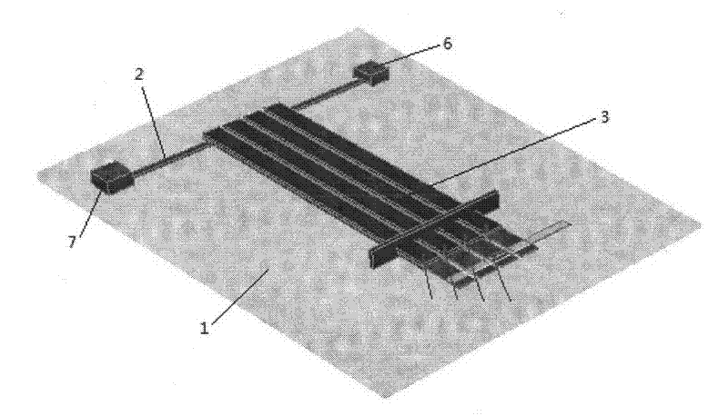
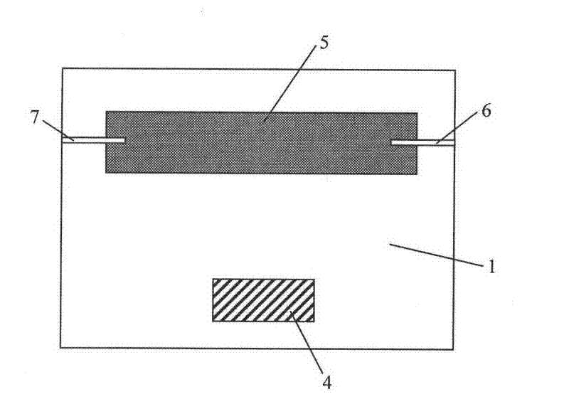
[0041]The micro-pump substrate and micro-fluid pipeline mold made of PMMA material were fabricated by micromachining method, and a 100 μm-deep micro-fluid pipeline bonding area and a certain depth of piezoelectric drive array slots were fabricated on the surface of the micro-pump substrate; while the micro-fluid pipeline mold The internal height of the pipe is 100 μm, and the wall thickness of the pipe is 300 μm; the two opening a...


PUM


Abstract

The invention provides a structure and a forming method of a travelling-wave valveless piezoelectric micropump of a multistage diffusion micro-flow pipeline. The structure of the travelling-wave valveless piezoelectric micropump comprises a micropump base, a micro-flow pipeline and a travelling-wave driving array, wherein the micropump base mainly comprises a driving array clamping groove, a micro-flow pipeline bonding area, a sample inlet and a sample outlet; the multistage diffusion micro-flow pipeline is made of a PDMS (Polydimethylsiloxane) material; a corresponding trapezoidal protrusion corresponding to each stage of diffusion structure is formed on the upper surface of the pipeline; the overall dimension of each corresponding trapezoidal protrusion is matched with the inside diameter of a diffusion pipe; the micro-flow pipeline and the micropump base are bonded together to form an integral pump body; the travelling-wave driving array is arranged in parallel by adopting dual piezoelectric bimorphs; one end of each piezoelectric bimorph is arranged on the corresponding trapezoidal protrusion on the surface of the micro-flow pipeline and is tightly contacted with the corresponding trapezoidal protrusion; and the other end of each piezoelectric bimorph is fixedly arranged on the micropump base. According to the travelling-wave valveless piezoelectric micropump disclosed by the invention, the multistage diffusion micro-flow pipeline is combined with the travelling-wave valveless piezoelectric micropump, so that the reverse reflow of the micro-flow pipeline is reduced and the output flow speed of the micropump is increased; and the travelling-wave valveless piezoelectric micropump has the characteristics of simple manufacturing process, small size, convenience and accuracy in flow control and the like and is suitable for manufacturing integrated micro-fluid chips.

Description

technical field [0001] The invention relates to a valveless piezoelectric micro-pump of a multi-stage diffusion micro-flow pipeline, the driving mode of which is traveling wave driving. Background technique [0002] Microfluidic (lab-on-a-chip) technology is one of the rapidly developing frontier fields of high-tech and interdisciplinary science and technology. It is an important technical platform for the research of signal detection and processing methods in life science, chemical science and information science. It can greatly reduce the consumption of biological samples and reagents in the biomedical field, and the analysis speed is doubled, and the cost is doubled; in the chemical field, it can use a small amount of samples and reagents on a chip to simultaneously Complete a large number of experiments; in the field of analytical chemistry, it turns large analytical instruments into square centimeter-scale analyzers. The components involved in the microfluidic chip inc...

Claims


Application Information

Patent Timeline
Patent Type & Authority Applications(China)
IPC IPC(8): F04B43/04
Inventor 刘国华张维战传娜李亭杨长锐杨锶毅王有里韩志龙曹宁牛文成
Owner NANKAI UNIV
Why Eureka
Try Eureka