
Ultra-compact High Pressure Ratio Diagonal Flow-Centrifugal Combined Compressor Structure

A centrifugal compressor and compressor technology, applied in the field of compressors, can solve the problems of large radial size of a two-stage centrifugal compressor, increase the windward area and weight of the engine, increase the difficulty of bearing design, etc. Reduce design difficulty and reduce processing effect

Active Publication Date: 2015-08-12
INST OF ENGINEERING THERMOPHYSICS - CHINESE ACAD OF SCI
View PDF6 Cites 0 Cited by
  • Summary
  • Abstract
  • Description
  • Claims
  • Application Information

AI Technical Summary

Problems solved by technology

However, due to the existence of the axial flow stage, the axial flow-centrifugal combined compressor is also difficult to avoid the above-mentioned disadvantages of the multi-stage axial flow compressor; the two-stage centrifugal compressor has the advantages of simple structure, few parts, high reliability and processing maintenance. Low cost and other advantages, however, the radial size of the two-stage centrifugal compressor is larger, which increases the windward area and weight of the engine, and increases the force acting on the bearing, which increases the difficulty of bearing design and reduces the life of the bearing

Method used


Image

  • Ultra-compact High Pressure Ratio Diagonal Flow-Centrifugal Combined Compressor Structure

Examples


Embodiment Construction

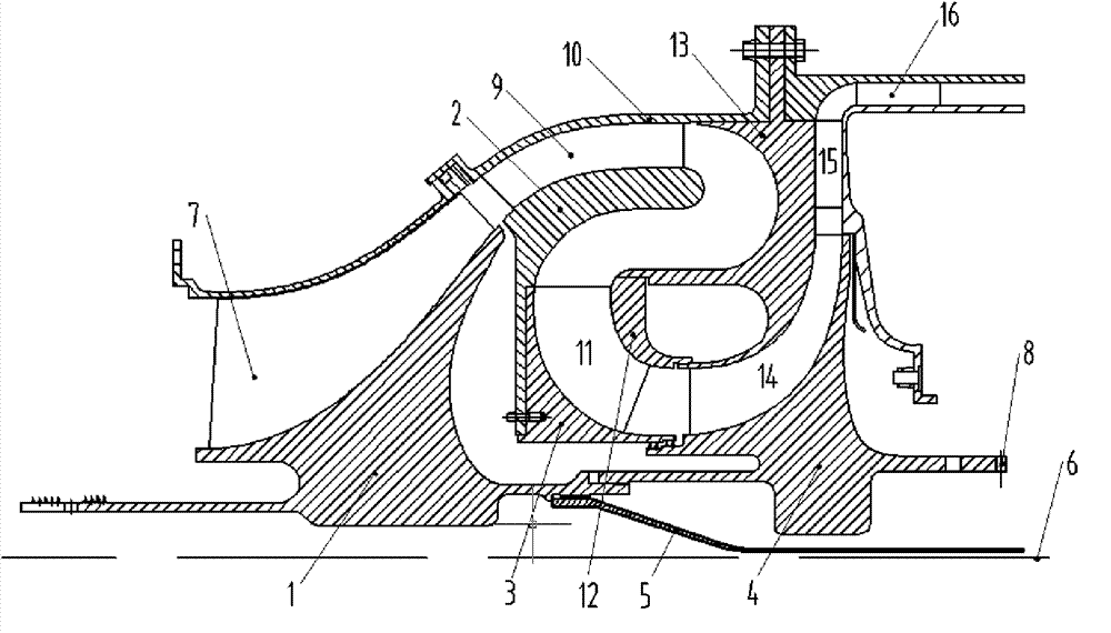
[0025] see figure 1 , the ultra-compact high-pressure ratio oblique flow-centrifugal combined compressor structure of the present invention consists of oblique flow impellers, small-diameter "S" elbows with rectifiers and return blades, centrifugal impellers, radial diffusers and axial diffusers The device is composed of six parts, wherein the oblique flow impeller is composed of the oblique flow impeller disc 1 and the oblique flow rotor blade 7, the centrifugal impeller is composed of the centrifugal impeller disc 4 and the centrifugal rotor blade 14, and the oblique flow impeller and the centrifugal impeller are connected by a section of radial Ultra-compact "S" elbow connection with small size, the inner wall of the "S" elbow is composed of inner wall part 2 and inner wall part 3, the outer wall of the elbow is composed of outer wall part 10, outer wall part 12 and outer wall part 13, the inlet of the elbow A row of rectifier vanes 9 is arranged and a row of recirculator v...


PUM


Abstract

The invention discloses an ultra-compact high-pressure ratio oblique flow-centrifuge combined compressor structure, which relates to the technology of the compressor. The ultra-compact high-pressure ratio oblique flow-centrifuge combined compressor structure comprises two stages, namely, an oblique flow compressor and a centrifuge compressor, wherein the first stage is the oblique flow compressor, and the second stage is the centrifuge compressor. The ultra-compact high-pressure ratio oblique flow-centrifuge combined compressor structure has the key points that the oblique flow compressor and the centrifuge compressor are connected by a small section of S-shaped small-diameter bend connection structure. The structure disclosed by the invention can be directly used for an aviation gas turbine engine and has various advantages of simple structure, few part, compact structure, high reliability, low processing and maintaining cost and the like, and according to the structure, the problems of low single stage compression ratio, multiple stages, heavy weight, high manufacture cost and big radial scale of a double-stage centrifuge compressor because the traditional medium and small aviation gas turbine engine in China adopts multistage axial flow compressors and axial flow-centrifuge combined compressors are solved.

Description

technical field [0001] The invention relates to the technical field of compressors, and is an ultra-compact high-pressure ratio oblique flow-centrifugal combined compressor structure, which is especially suitable for high-performance aviation gas turbine engines. Background technique [0002] The biggest difference between various types of small and medium thrust aviation gas turbine engines is reflected in the difference in the type of compressor components, which is different from the structural form of a multi-stage axial flow compressor with large flow rate and high pressure ratio used in large thrust aviation engines, and the compression system of small and medium thrust aviation engines adopts Combined compressor. However, there are also full-axial flow compressors, such as WS500, whose high-pressure compressor uses a 5-stage axial flow compressor. The advantages of multi-stage axial flow compressors are smooth flow channels and high efficiency, but the disadvantages a...

Claims


Application Information

Patent Timeline
Patent Type & Authority Patents(China)
IPC IPC(8): F04D25/16
Inventor 卢新根朱俊强赵胜丰
Owner INST OF ENGINEERING THERMOPHYSICS - CHINESE ACAD OF SCI
Learn More